
Er Diagram Generalization Is Represented By
Represented by a rectangle. To delete a particular.
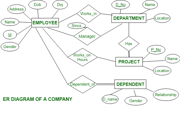
Er Diagram Of A Company Geeksforgeeks
It is represented by dashed oval in an ER Diagram.
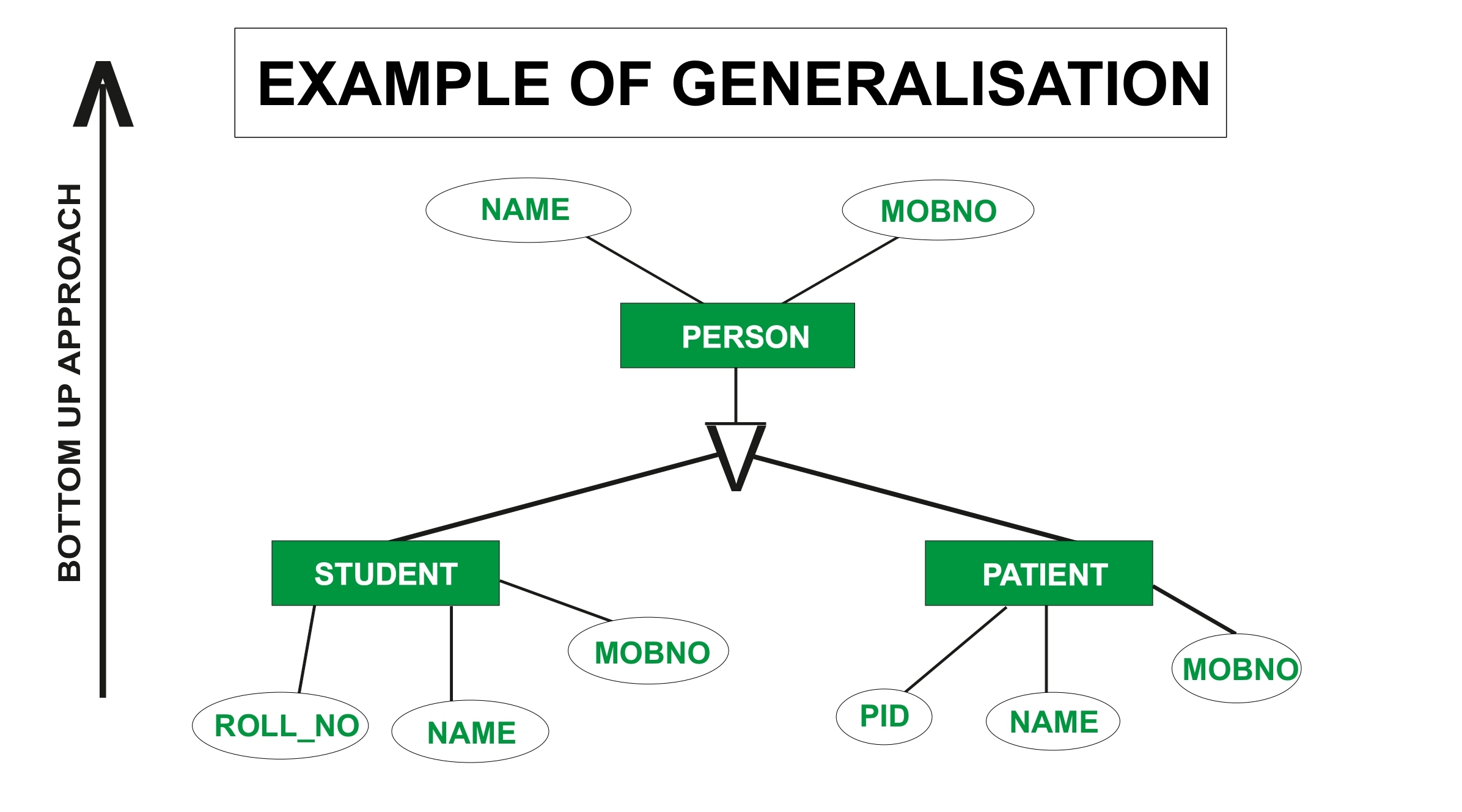
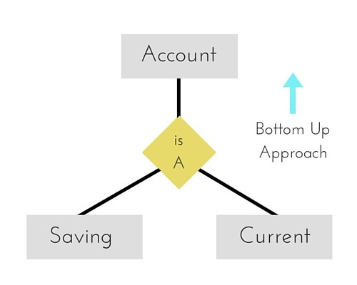
Er diagram generalization is represented by. These diagrams are the graphical representation of the movement of data and data. ER diagrams are visual tools that are helpful to represent the ER model. Reverse process of specialization bottom-up.
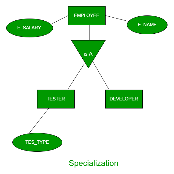
In E-R diagram generalization is represented by Options is. In E-R diagram generalization is represented by A Ellipse B Rectangle C Triangle D Dashed ellipse. All the world is a set of things.
In E-R diagram generalization is represented by - MCQSCENTER. In E-R diagram generalization is represented by. A database schema in the ER model can be represented pictorially Entity-Relationship diagram.
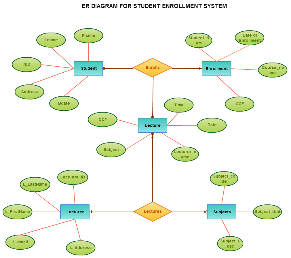
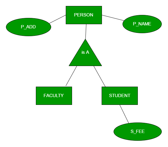
For example a school system may include students teachers major courses subjects fees and other items. In E-R diagram generalization is represented by Ellipse Dashed ellipse Rectangle Triangle. An entity can be a person place event or object that is relevant to a given system.
Er Diagram Generalisation Is Represented By ER is actually a great-levels conceptual info design diagram. This is a Most important question of gk exam. The major entities within the system scope and the inter-relationships among these entities.
In E-R Diagram relationship type is represented by. For example Phone_No can be more than one for a given student. One of the most basic symbols of an ER diagram is the entity.
Network model between the tables that connect them. In those cases a relationship with its corresponding entities is aggregated into a higher level entity. ER modeling helps you to assess info specifications systematically to generate a properly-designed data base.
In E-R diagram generalization is represented by. A collection of similar entities eg all movies. He aimed to use an ER model as a conceptual modeling approach.
These diagrams are most frequently used in enterprise agencies to create. Basis for deriving a relational database schema from an ER diagram. In ER diagram multivalued attribute is represented by double oval.
Rectangles are named with the entity set they represent. In E-R diagram generalization is represented by. Chen ERD Symbols.
In E-R diagram generalization is represented by Options is. The total participation by entities is represented in E-R diagram as. Entities are represented in ER diagrams by a.
Which is specialization and generalization in ER diagram. Peter Chen was the one responsible for coming up with the Chen ERD notation. Of Computer Science UC Davis 2.
In E-R diagram generalization is represented by. In an E-R diagram attributes are represented by. In E-R diagram generalization is represented by - Basics of computer science and Engineering Previous Question.
Thus the generalization is Functional dependencies are a generalization of. An ER diagram is not capable of representing relationship between an entity and a relationship which may be required in some scenarios. Enhanced ER or EER diagrams Diagrammatic technique for displaying these concepts in an EER schema Subtype or subclass of an entity type Subgroupings of entities that are meaningful Represented explicitly because of their significance to the database application.
Related Questions on Databases. Entities are represented by means of rectangles. DBMS Objective type Questions and Answers.
For More Databases MCQ Click Here. In ER diagram composite attribute is represented by an oval comprising of ovals. Aggregation is an abstraction through which we can represent relationships as higher level entity sets.
None of the above. For example Person age is a derived attribute as it changes over time and can be derived from another attribute Date of birth. Peter Chen proposed ER Diagram in 1971 to create a uniform convention that can be used for relational databases and networks.
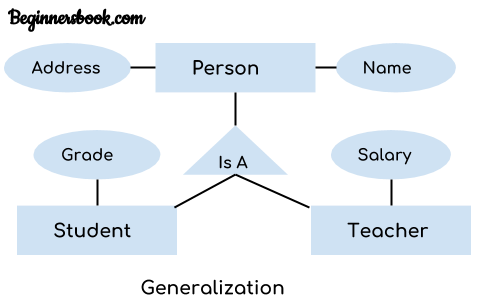
Entity Relationship ER Modeling. Dashed ellipse 2. Specialization And Generalization In Er Diagram Entity Relationship Diagrams are the most useful tools to speak throughout the entire system.
Entity-Connection version is based on the notion of true-community entities and also the relationship between them. This is a Most important question of gk exam. Any object for example entities attributes of an entity relationship sets and attributes of relationship sets can be represented with the help of an ER diagram.
Dashed ellipse 2. He was one of the first individuals who used ERD in database design. To further elaborate on it keep reading.
An entity is one object it is described via its attributes. 80 The method of access which uses key transformation is known as. Let us now learn how the ER Model is represented by means of an ER diagram.
A Dada manipulation command the combines the records from one or more tables is called. An ERD contains different symbols and connectors that visualize two important information. They have their attributes and relationships.
Electronics Bazaar is one of best Online Shopping Store in India. Entity Relationship Diagram also known as ERD ER Diagram or ER model is a type of structural diagram for use in database design. The entity relationship set is represented in E-R diagram as.
For example Person age is a derived attribute as it changes over time and can be derived from another attribute Date of birth. Multivalued Attribute An attribute consisting more than one value for a given entity.
Difference Between Generalization And Specialization In Dbms Geeksforgeeks
Dbms Generalization
Generalization Specialization And Aggregation In Er Model Geeksforgeeks

Specialization Generalization And Aggregation Csveda

Specialization Top Down And Generalization Bottom Up Approach Entity Relationship Example Relationship Diagram Tutorial Diagram
Generalization Specialization And Aggregation In Er Model Geeksforgeeks
Generalization Specialization And Aggregation In Er Model Studytonight

25 Project Management Process Pdf Enadho Relationship Diagram Project Management Templates Project Management
Entity Relationship Diagram Erd Er Diagram Tutorial


Post a Comment