Er Diagram Partial Key
Indicating primary key status can be done by underlining the attribute in question. What constraints do the partial key and the identifying relationship of the weak entity type specified in this diagram.

Entity Relationship Er Diagram Of Busan Traffic Data Download Scientific Diagram
How to Draw ER Diagrams.
Er diagram partial key. An entity set with a primary key is called a strong entity set. In the ER diagram the relationship between two strong entity set shown by using a diamond symbol. Map the following ER diagram into a relation schema.
When you first start making E-R diagrams the number. ER diagrams help users to model their databases by using various tables that ensure that the database is organized efficient and fast. Keys are used to link various tables in a database to each other in the most efficient way possible.
Create rectangles for all entities and name them properly. Connect them using a line and add a diamond in the middle describing the relationship. Any object for example entities attributes of an entity relationship sets and attributes of relationship sets can be represented with the help of an ER diagram.
Let us now learn how the ER Model is represented by means of an ER diagram. Choose as the primary key of E the collection of attributes arising from some key of E. If you re unfamiliar with entities and attributes you may want to read Intro to the E-R Diagram first.
The ER diagram is a way to model a database in an organized and efficient way. Other keys you may come across include foreign and partial keys. Notice that cl is a partial.
In chens notation partial keys discriminator were shown as dashed lines how are they shown in uml er entity-relationship diagram. Do not forget to specify the constraints related to the foreign keys if any. The constraints of the identifying relationship are.
An entity set without a primary key is called a weak entity set Represented by a double rectangle Corresponding relationship represented with a double diamond A discriminator partial key distinguishes among elements of a weak entity set. Notice that cl is a partial key for the entity and al is a partial key for the entity A. In an subclass hierarchy only the root entity set has a key and it must serve as the key for allentities in the hierarchy.
If some courses are not enrolled by any of the student the participation of course will be partial. Entities are represented by means of. We usually designate one as the primary key.
The constraint of the partial key Branch - no is that we need to combine Branch - no with Code the key from its owner entity set Bank to uniquely identify a Bank_Branch. Primary Key of the Loan along with the partial key would be used to identify the records. Nameis Key for Beers Beers Ales isa name manf color Example.
Partial Key. In the below ER Diagram Payment is the weak entity. Primary keys allow entity types and relationship types to be expressed uniformly as tables.
By nature it is an abstract visualization the first step in the design process towards creating a logical and functional database. Sebelum membuat Diagram E-R tentunya kita harus. Loan Payment is the identifying relationship and Payment Number is the partial key.
ER Diagram Keys. Partial Key attributes are represented with dotted lines. Manages is said to be totalvs.
An ER schema can be represented by a collection of tables which represent contents of the database instance. The relationship between one strong and a weak entity set shown by using the double diamond symbol. Below points show how to go about creating an ER diagram.
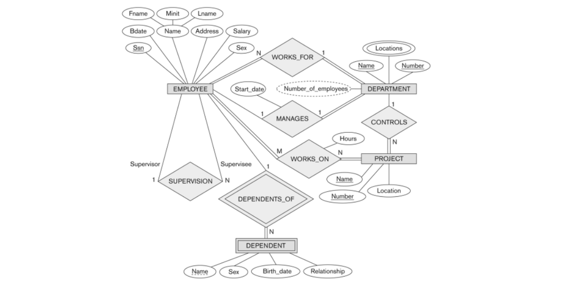
This makes it clear which column in the child table is the foreign key to the parent table. Translating ER Diagrams with Key Constraints Map relationship to a table. An employee is assigned to one department but may work on several projects which are not necessarily controlled by the same department.
It is very usable in tables which millions of data or rows. In ER Modelling Keys are used for indexing. Identify relationships between entities.
Lets take an example of a table EMPLOYE with the fields EMP_ID EMP_F_NAME EMP_L_NAME EMP_PHNO EMP_EMAI. An Entity set E can have multiple keys. When drawing ER diagrams I have used the following graphical convention.
Keys are one way to categorize attributes. This tutorial explains how to create and illustrate an primary key for an ER diagram using Dia Diagram Software. A key is a way to categorize attributes in an E-R diagram.
Through keys one can easily access any row without wasting much time and efficiency. 51 b2 bt m - a1 c1 m a2 - ut c2. Every did value in Departments table must appear in a row of the Manages table with a non-null ssn value lot name dname did budget since Manages.
Map the following ER diagram into a relation schema. Total participation is shown by double line in ER diagram. Its one or more attributes that uniquely identify a weak entity for a given owner entity.
An entity should appear only once in a particular diagram. Dengan kata lain Diagram E-R menggambarkan arti dari aspek data seperti bagaimana entity-entity atribut-atribut dan relationship-relationship disajikan. Identify all the entities in the system.
If each student must enroll in a course the participation of student will be total. Partial Participation The entity in the entity set may or may NOT participate in the relationship. In a weak entity set it is a combination of primary key and partial key of the strong entity set.
Chapter Outline Overview of Database Design Process Example Database Application COMPANY ER Model Concepts Entities and Attributes Entity Types Value Sets and Key Attributes Relationships and Relationship Types Weak Entity Types Roles and Attributes in Relationship Types ER Diagrams - Notation ER Diagram for COMPANY Schema. Label the relationship lines with the foreign key column names like so. Perangkat konseptual menjadik sebuah diagram yaitu diagram ER Entity Relationship Diagram Entity-Relationship melengkapi penggambaran grafik dari struktur logika.
For each entity and relationship type a unique table can be derived which is assigned the name of the corresponding entity or relationship type. We store each employees name first last MI Social Security number SSN street address salary sex gender and birth date. Draw an ERD for the following description.
With respect to the University E-R diagram in Figure 310 this step leads us to the following partial relational schema. Keys in ER Diagrams Underline the key attributes. A weak entity has whats called a partial key.
Creating an entity-relationship ER model is to visually represent the structure of a business database where data equates to entities or objects that are linked by defined relationships expressing dependencies and requirements.

How To Identify A Strong Vs Weak Relationship On Erd Stack Overflow

Entity Relationship Diagram Staruml Documentation

Tugas 5 Entity Relationship Siti N Febriyani Universitas Negeri Gorontalo

Key Attributes In Er Diagrams In 2021 Diagram Data Science Attributes
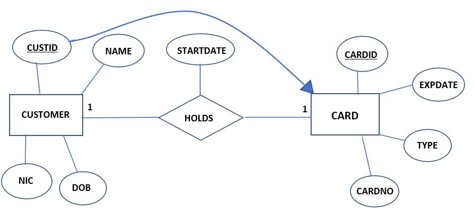
Drawing Er And Eer Diagrams Relational Mapping By J Riyana Nerd For Tech Medium
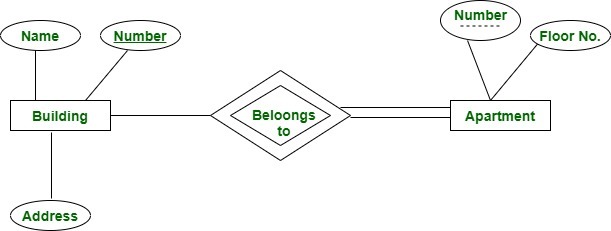
Partial Unique Secondary Composite And Surrogate Keys In Dbms Geeksforgeeks
An Er Diagram Illustrating 3 Entities Professors Students And Download Scientific Diagram

Entity Relationship Diagram Common Erd Symbols And Notations Relationship Diagram Diagram Erd

Er Diagram Symbols And Notations Edrawmax Online
What Is A Partial Key In Database Systems Quora
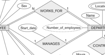
Database Modeling Entity Relationship Diagram Erd Part 5 By Omar Elgabry Omarelgabry S Blog Medium

Partial Er Diagram Extracted From The Student Registration Subsystem At Download Scientific Diagram
Database Modeling Entity Relationship Diagram Erd Part 5 By Omar Elgabry Omarelgabry S Blog Medium

Post a Comment