
Mollier Diagram Oxygen
Figure A-27 Generalized Compressibility Chart P R 1. Temperature is easy to measure.

Mollier Diagram Spirax Sarco Pdfcoffee Com
They are essential small molecules for life matter and energy.
Mollier diagram oxygen. Mollier diagrams are named after Richard Mollier. Air is a mixture of mostly oxygen nitrogen and water vapor. HELIUM Density Specific Volume Compressibility Factor Specific Heat C C Specific Heat Ratio CC Specific Heat Cs of Liquid Helium at Saturation Viscosity Gas Thermal Conductivity Internal Energy Charts Velocity of Sound Enthalpy.
Thermodynamic Properties - Main. Results of the computational program are presented in tabular and graphic form the latter being a conventional Mollier diagram in which specific enthalpy is plotted against specific entropy with cross plots of. The paper describes the process.
Figure A-31 Generalized Entropy Chart. In addition to the standard vapour liquid-vapour and liquid regions that can be seen in the Mollier diagram of any conventional refrigerant the region below the critical point supercritical phase and the regions below the. Oxygen O 2 02598 0918 0658 1395 Propane C 3H 8 01885 16794 14909 1126 Steam H 2O 04615 18723 14108 1327 Note.
Oxygen Nitrogen And Argon Vapor Pressure Curves. Figure A-30 Generalized Enthalpy Chart. Oxygen sensor replacement e91 e92 e93 crown markings of a medical oxygen cylinder high mollier diagram engineering toolbox how vinegar is made making history used product fuel the boeing 737 technical site diy glass aquarium plans and step by step instructions oxygen stock photos royalty free oxygen images.
For the following fluids only software libraries are available. A MOLLIER DIAGRAM FOR THE INTERNAL-COMBUSTION ENGINE H. The systems compared are a coalair system with a thermal input of 2000 MWth and two coaloxygen systems one with an input of 2000 MWth and one with 6600 MWth.
Adapted from Canjar LN. Pressure-enthalpy diagram log P-h Mollier diagram When working with CO 2 for refrigeration an expanded P-h diagram must be used ie. Oxygen nitrogen and hydrogen have been at the core of the companys activities since its creation in 1902.
Oxygen O 2 02598 0918 0658 1395 Propane C 3H 8 01885 16794 14909 1126 Steam H 2O 04615 18723 14108 1327 NoteThe unit kJkgK is equivalent to kJkgC. The unit kJkgK is equivalent to kJkg8C. And presents Mollier diagrams for the two systems.
They embody Air Liquides scientific territory. Mollier Psychrometric Chart For Nitrogen Acetone System At 100. Specific isobaric heat capacity.
PressureEnthalpy Diagrams for Various Compounds FIGURE D1 Oxygen pressureenthalpy diagram. Richard Mollier 1863-1935 was a professor at Dresden. Air Liquides ambition is to lead its industry deliver long-term performance and contribute to sustainability.
Figure A-26 Mollier Diagram for Steam. The heat or energy content is difficult to measure directly so the diagram is cunningly distorted to give the illusion of being based on the relationship between temperature and relative humidity and water vapour content. The gas phase of the heterogeneous chemical system like the homogeneous gas phase comprises seven gaseous silicon-oxygen species.
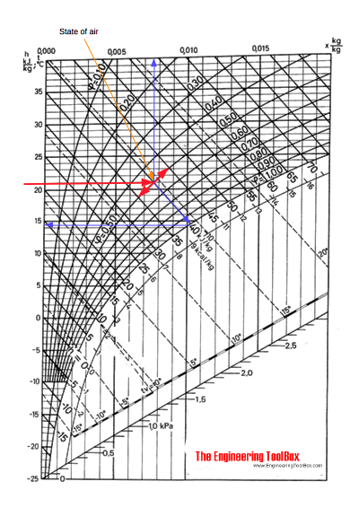
The Mollier diagram also called the ix diagram is based on the relationship between heat content and water vapour content of air. Figure A-28 Compressibility Chart Low-Pressure Range. An Unbiased Viewpoint Retail Modern Tire Dealer.
The Mollier diagram is a graphic representation of the relationship between air temperature moisture content and enthalpy and is a basic design tool for building engineers and designers. Kitchen Prep Table Nitrogen Pressure Temperature Chart. Chemical and Process Thermodynamics3E by Kyle B.
And Manning FS Thermodynamic Properties and Reduced Correlations for Gases Gulf Publishing Houston. A typical chart covers a pressure range of 0011000 bar and temperatures up to 800 degrees Celsius. Kyle Chemical and Process Thermodynamics 3rd ed.
Pt 008871336 psi. Cen98179_ch18_ap01_897-946indd 899 112213 408 PM Confirming Pages. Oxygen O 2 31999 006206 03353 2786 736 125 Propane C 3H 8 44097 004504 02433 6659 617 320 Propylene C 3H 6 42081 004719 02550 6569 670 290 Sulfur dioxide SO 2 64063 003100 11675 7752 1143 195 Tetrafluoroethane R-134a CF 3CH 2F 10203 001946 01052 6736 5887 319 Trichlorofluoromethane R-11 CCl.
Oxygen Desktop applications and libraries are provided for calculation of thermodynamic and transport properties of water and steam and humid moist air. Dead Horse Beatings Ensue Within Page 5 Overclock An. Temperature is easy to measure.
This handbook is organized as follows. Mollier Charts Pressure-Enthalpy with constant Temperature Density and Entropy Lines Mollier diagram is a graphical representation of the thermodynamic properties and states of materials involving Enthalpy on one of the coordinates. It shows enthalpy H displaystyle H in terms of internal energy U displaystyle U pressure p displaystyle p.
22 The structure of the Mollier diagram 9 221 Temperature scale 9 222 Absolute humidity scale 9 223 Vapor pressure scale 9 224 Saturation pressure saturation line 10 225 Dew point temperature saturation temperature 10 226 Lines having a constant relative humidity 11 227 Temperature humidity pressure 11. Pt 611657 Pa 000611657 bar Triple-point pressure. Compares flame temperature electrical conductivity and specific enthalpy.
An enthalpyentropy chart also known as the HS chart or Mollier diagram plots the total heat against entropy describing the enthalpy of a thermodynamic system. EBERHARDT Massachusetts Institute of Technology Cambridge Massachusetts The limitations of thermodynamics as a tool for studying chemical reactions have been so adequately emphasized in college courses in physi- cal chemistry as to have convinced many auto- motive. - Selection from Chemical Engineering Fluid Mechanics 3rd Edition Book.
The heat or energy content is difficult to measure directly so the diagram is cunningly distorted to give the illusion of being based on the relationship between temperature and relative humidity and water vapour content. The Mollier diagram also called the ix diagram is based on the relationship between heat content and water vapour content of air. Carbon dioxide R134a R123.
The Mollier diagram is a variant of the psychrometric chart. Figure A-29 Compressibility Chart High-Pressure Range. Upper Saddle River NJ.
Figure A14EP-h diagram for refrigerant-134a Table A16EProperties of the atmosphere at high altitude Table A17EIdeal-gas properties of air Table A18EIdeal-gas properties of nitrogen N 2 Table A19EIdeal-gas properties of oxygen O 2 Table A20EIdeal-gas properties of carbon dioxide CO 2 Table A21EIdeal-gas properties of carbon monoxide CO. Taining to helium hydrogen oxygen and nitrogen. Adapted by permission of Pearson Education Inc Upper Saddle River NJ.

H X Diagram Pdf The Mollier Hx Diagram Quantities Air Density R The Vertical

Appendix D Pressure Enthalpy Diagrams For Various Compounds Chemical Engineering Fluid Mechanics 3rd Edition Book

Mollier Chart Diagram Hvac Psychrometric Analysis Software Analysis Hvac Diagram
Moist Air The Mollier Diagram
Using Mollier S Chart What Is The Final Pressure And Temperature Of Steam When It Is Isentropically Expanded From Enthalpy Of 3500 Kj Kg And 30 Bar Pressure To Enthalps Of 2900 Kj Kg Quora

E Mollier Diagram With The Process Temperatures And Vapour Pressure For Download Scientific Diagram

Step By Step 9 Power Conditioning Uninterruptible Power Supply Power Ups

Appendix D Pressure Enthalpy Diagrams For Various Compounds Chemical Engineering Fluid Mechanics 3rd Edition Book
Moist Air The Mollier Diagram

Mollier Diagram Spirax Sarco Pdfcoffee Com

Mollier H X Diagram With Estimated Greenhouse Dehumidification Process Download Scientific Diagram

Comparing Mollier Diagrams And The Psychrometric Charts Psychrometric Chart Chart Diagram

Appendix D Pressure Enthalpy Diagrams For Various Compounds Chemical Engineering Fluid Mechanics 3rd Edition Book

From 6 In The Mollier Diagram Water Splitting Starts From Point A Download Scientific Diagram

Post a Comment