
Mollier Diagram Regions
For saturated steam condition the dryness fraction of the steam should be between 0 and 1. For superheated steam the dryness fraction of the steam should be greater than 1.
2
The axes of the.

Mollier diagram regions. Detail Diagram Mollier PDF dapat kamu nikmati dengan cara klik link. Download Diagram Mollier PDF 2000 MB - SamPDF Unduh Diagram Mollier PDF secara gratis di SamPDF. Extensive properties in superheated vapor state vapor region.
Mollier The ix-diagram for airwater vapor mixtures 1929 3 13 Oblique coordinates are advantageous for the ix-diagram. First we find the condition for saturated steam. The process transforming a Mollier diagram to a psychrometric chart is shown below.
Mollier diagrams can be plotted for different fluids. As the pressure increases the saturation temperature increases and so the slope of the isobar also increases. Enthalpy diagram can be developed for R-22 similar to the one illustrated for water in Figure 2Using such a diagram you can plot the performance of any air conditioning system and identify all the work done by the system.
Hence the constant pressure lines diverge from one another. Mollier diagram for common use in refrigeration. Dryness fraction of steam means the mass ratio of a.
Mollier Diagrams The Mollier diagram is a very useful tool. The diagram was created in 1904 when Richard Mollier plotted total heat against entropy. For superheated steam the dryness fraction of the steam should be greater than 1.
D Both positive and negative slopec Not positive nor negative slope. It depicts properties of water and steam for pressures up to. A main H-S coordinate system Enthalpy-Entropy is used.
The liquid region is also known as the sub-cooled region. Mollier diagram is enthalpy h versus entropy s plot. Conversion factors are listed below.
Constant pressure lines n the superheated region of the Mollier diagram will have a A positive slope. It can be used to depict the various processes associated with the tur bine set. For superheated steam the dryness fraction of the steam should be greater than 1.
The steam table and mollier diagram of superheated steam are given as shown in Table The lower portion contains the values of wet steam whereas the upper portion contains the values of superheated. First it has to be reflected in a vertical mirror then rotated 90 degrees. The psychrometric chart is a variant of the Mollier diagram used in some parts of the world.
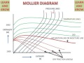
This video explains the various lines and regions that make up a Mollier diagram that is an enthalpy-entropy diagram. Using the Mollier diagram we can find out the conditions required for saturated and superheat regions. It consists of a family of constant pressure lines constant temperature lines and constant volume lines plotted on enthalpy versus entropy coordinates.
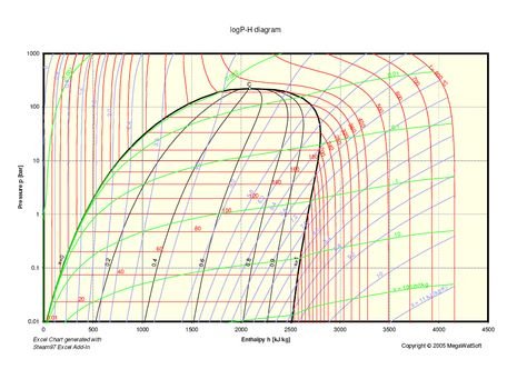
Temperature is easy to measure. The following is the Mollier diagram for water and steam. For saturated steam condition the dryness fraction of the steam should be between 0 and 1.
It may also be used quantitatively for various calculations. The heat or energy content is difficult to measure directly so the diagram is cunningly distorted to give the illusion of being based on the relationship between temperature and relative humidity and water vapour content. Constant pressure lines in the superheated region of the Mollier diagram will have.
In this region there are vertical temperature lines which increase as enthalpy is increased. First we find the condition for saturated steam. Typically the Mollier chart covers pressure in the range of 001 to 1000 bar and up to 800 oC temperature.
Figure 8 is a simplified P-H diagram illustrating the constant temperature lines. Download Diagram Mollier PDF 2000 MB - SamPDF SamPDF. They permit a better use of the graph area and the most important families of curves are clearly represented.
Using the Mollier diagram we can find out the conditions required for saturated and superheat regions. The Mollier diagram is the representation of the properties of water and water vapor. Dry steam to water particles in steam.
How to Use the Mollier Diagram. The critical isobar is a tangent at the critical point. B A negative slope.
Mollier diagram - thermodynamics Mechanical Engineering. Following the above formula for the enthalpy the isotherms are straight lines. Your consideration of Mollier diagrams in this course will be limited to a qualitative look at the turbine set.
At the 1923 Thermodynamics Conference held in Los Angeles it was decided to name in his honor as a. The most common of these are inches of water inches of mercury millimeters of mercury and microns of mercury. It is also called as H-diagram.
A simplified Mollier diagram is commonly used to represent refrigerating machine cycles where the region that contains solid or solid-liquid left area and the region below the triple point 52 bar are not represented. Wet steam to dry steam b. None of the above.
For saturated steam condition the dryness fraction of the steam should be between 0 and 1. Both positive and negative slope. The Mollier diagram also called the ix diagram is based on the relationship between heat content and water vapour content of air.
147 psia 408 inches of water 147 psia 299 inches of mercury 1 inch of mercury 254 millimeters of mercury 1 millimeter of mercury 103microns of mercury. A Mollier diagram for water is shown in Figure 61. The curves break up the diagram into three regions 1 Liquid 2 Vapor and 3 Mix.
Cooling capacity normally is determined at 80F dry-bulb67F wet-bulb indoor and 95F dry-bulb outdoor temperatures. Mollier diagram is chart drawn between enthalpy H on ordinate and entropy or S on abscissa. The slope of the constant pressure line on an h-s curve is equal to absolute temperature and due to this reason the constant pressure lines.
First it is necessary to find whether the steam is wet dry saturated or superheated. Using the Mollier diagram we can find out the conditions required for saturated and superheat regions. First we find the condition for saturated steam.
Mollier diagram is the h-s diagram of pure substance. The dryness fraction x gives the fraction by mass of gaseous water in the wet region the remainder being droplets.
Analysis Of The Mollier Diagram To Simplify The Calculations Of Thermodynamic Magnitudes Steemit
Analysis Of The Mollier Diagram To Simplify The Calculations Of Thermodynamic Magnitudes Steemit


Mollier Diagram Of Air Download Scientific Diagram
Mollier Diagram With Lp Steam Expansion Line And Thermodynamic Regions Download Scientific Diagram
Analysis Of The Mollier Diagram To Simplify The Calculations Of Thermodynamic Magnitudes Steemit

Mollier Diagram An Overview Sciencedirect Topics

Mollier Chart How To Read Youtube
Analysis Of The Mollier Diagram To Simplify The Calculations Of Thermodynamic Magnitudes Steemit

Mollier Diagrams Advanced Steam Traction
 Reviewed by admin
on
November 27, 2021
Rating:
Reviewed by admin
on
November 27, 2021
Rating:

Post a Comment