
Er Diagram N Meaning
Entity-Relationship ER Diagrams Lecture 7 February 11 2018 Entity-Relationship ER Diagrams 1. Entity attributes primary and foreign keys are defined as a part of the diagram.

Martin Style Cardinality Erd Relationship Diagram Diagram Relationship
So that an ER diagram can express the overall logical structure of a database graphically.
Er diagram n meaning. Below are pre-drawn ER diagram symbols in Edraw ER diagram software including entity weak entity strong relationship weak relationship attribute derived attribute constraint and participation etc. E1 is an entity having Entity Type Student and set of all students is called Entity Set. First ER diagrams are easy to understand and do not require a person to undergo extensive training to be able to work with it efficiently and accurately.
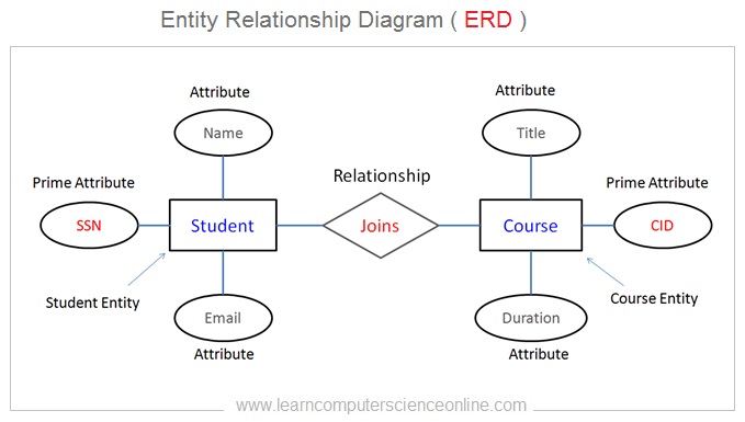
Today we will be briefly discussing them and their notation styles. ER-diagram is a tool used for database modeling which allows to determine data and relationships among the data. In ER diagram Entity Type is represented as.
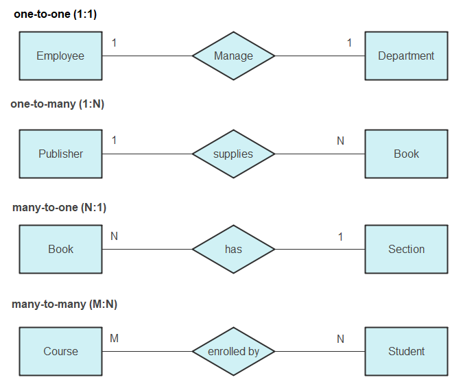
One-to-many When more than one instance of an entity is associated with a relationship it is marked as 1N. An entity-relationship ER diagram is created based on these three types which are listed below. In relational database design a one-to-many 1N relationship exists when for one instance of entity A there exists zero one or many instances of entity B.
An Entity is an object of Entity Type and set of all entities is called as entity set. Keys are used to link various tables in a database to each other in the most efficient way possible. An ER diagram shows the relationship between the entity sets.
This means that designers can use ER diagrams to easily communicate with developers customers and end users regardless of their IT proficiency. CS3200 Database Design Spring 2018 Derbinsky Outline 1. M - ordinality - describes the minimum ordinal vs mandatory N - cardinality - describes the miximum.
An ERD is a conceptual and representational model of data used to. A one-to-many relationship is represented by adding 1 near the entity at left hand side of relation and N is written near the entity at right side. The main components of E-R model are.
What Is an ER Diagram. In relational database design a one-to-one 11 relationship exists when zero or one instance of entity A can be associated with zero or one instance of entity B and zero or one instance of entity B can be associated with. Entity set and relationship set.
MN m and n0123 zero or more to zero or more many to many 11 one to one. An entity-relationship model ER space model describes the structure of a database with the help of a diagram which is known as the Entity-relationship diagram ER diagram. But for one instance of entity B there exists zero or one instance of entity A.
1N n0123 one to zero or more. An entity relationship diagram ERD is a popular type of database diagram that clearly displays the system entities and their internal relationships. For example Roll_No Name DOB Age.
ER-diagram contains entities attributes of the entities and the relationships between them. The major entities within the system scope and the inter-relationships among these entities. These diagrams help to detail data storages and to document all the properties of designed system.
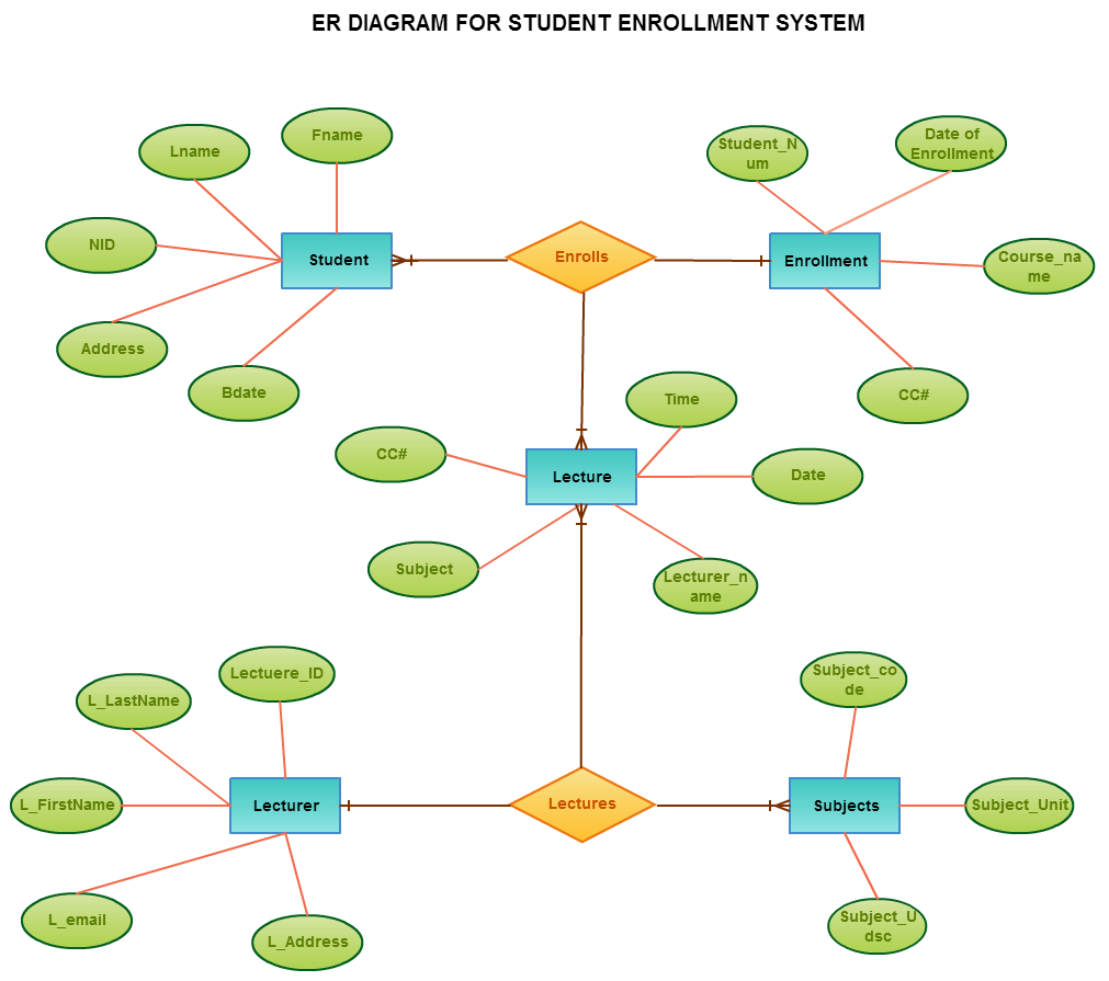
Judging by the names of entities relationships using common sense ie guessing because the diagram doesnt say lecturer-Teaches-student would be MN. ER diagrams help users to model their databases by using various tables that ensure that the database is organized efficient and fast. The following image reflects that only one instance of entity on the left and more than one instance of an entity on the right can be associated with the relationship.
ERD diagrams are commonly used in conjunction with a data flow diagram to display the contents of a data store. ER Diagrams are most often used to design or debug relational databases in the fields of software engineering business information systems education and research. An entity-relationship diagram ERD is a data modeling technique that graphically illustrates an information systems entities and the relationships between those entities.
In other words ER diagrams help to explain the logical structure of databases. Other type of notation will have dash at LHS of relation and three arrow kind of. An Entityrelationship model ER model describes the structure of a database with the help of a diagram which is known as Entity Relationship Diagram ER Diagram.
See this article right now to explore more about the ER Diagram field including advantages usages and how-to tips. An ER model is a design or blueprint of a database that can later be implemented as a database. What is ER Diagram.
Attributes are the properties which define the entity type. What does the letter N on a relationship line in an Entity Relationship diagram mean. An ERD contains different symbols and connectors that visualize two important information.
An Entity Relationship ER Diagram is a type of flowchart that illustrates how entities such as people objects or concepts relate to each other within a system. The Chens ERD notation is still used and is considered to present a more detailed way of representing entities and relationships. ER diagrams are created based on three basic concepts.
Entity Relationship Diagram also known as ERD ER Diagram or ER model is a type of structural diagram for use in database design. But also by common sense it is redundant because we would expect that the lecturers teaching a student would be derivable from the lecturers teaching the subjects of the classes the student attends. Use also ConceptDraw DIAGRAM enhanced with powerful Entity-Relationship Diagram ERD solution to draw your own ER.
ER Diagram stands for Entity Relationship Diagram also known as ERD is a diagram that displays the relationship of entity sets stored in a database. They help us to visualize how data is connected in a general way and are particularly useful for constructing a relational database. There are several ER diagram notations exist and only differ a little.
Entities attributes and relationships. An entity-relationship diagram also known as ERD depicts the data model of a system or its part using entities that represent data types and relationships that define the dependencies between entitiesThe ER diagrams are used for designing database schemas.

The Entity Relationship Diagram For The Movie Recommendation System Download Scientific Diagram
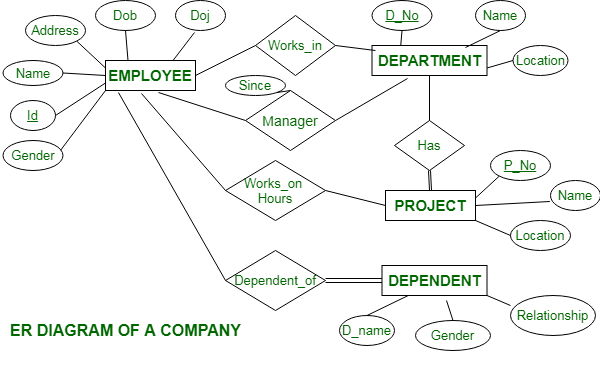
Er Diagram Of A Company Geeksforgeeks
Er Diagram Symbols And Notations Edraw
Entity Relationship Diagram Erd Explained Er Model In Dbms
Entity Relationship Diagram Erd Er Diagram Tutorial

Entity Relationship Diagram Symbols And Meaning Crow In 2021 Relationship Diagram Diagram Meant To Be

Er Diagram Person In An Organizational Unit Download Scientific Diagram

Standard Flowchart Symbols And Their Usage Basic Flowchart Symbols And Meaning Workflow Di Relationship Diagram Workflow Diagram Electrical Circuit Diagram

Airport Erd Relationship Diagram Diagram Templates

Post a Comment