
Mollier Diagram R134a
But if you find yourself working with steam the pressure enthalpy diagram for water the pressure-enthalpy diagram illustrated below or the temperature-entropy diagram illustrated to the left or the entropy-enthalpy diagram or Mollier. Using the refrigerant R134a operating with an evaporation temperature of 3c and a condensation temperature of 35c will lead to.

Pressure Enthalpy Diagram Of Thermodynamic Cycle R134a Download Scientific Diagram
It uses for this example evaporating and condensing temperatures of 0F and 120F.
Mollier diagram r134a. Mungkin sebagian diantara kita ada yang belum tahu atau lupa-lupa ingat ketika membaca Diagram Mollier. The Mollier diagram coordinates are enthalpy h and humidity ratio x. Mollier diagram and glide 41.
Figure A9E T-s diagram for water Figure A10EMollier diagram for water Table A11ESaturated refrigerant-134a Temperature table Table A12ESaturated refrigerant-134aPressure table Table A13ESuperheated refrigerant-134a Figure A14EP-h diagram for refrigerant-134a Table A16EProperties of the atmosphere at high altitude. Thermodynamic diagrams are very useful tools for folks working in the HVAC industry. R134a mollier chart pdf à Berndt Wischnewskiã Richard-Wagner-Str.
R134a R290 R22 R407C R717 R507 R410A R22 NH 3 R404AR507 Propane R407C R410A R134a R22 its near neighbors Comparison of Simple Cycle EER R22 R134a R290 R407C R507 R410A 080 085 090 095 100 105 110 EER Relative to R22 ARI CHEER. The psychrometric chart is probably the most common. The ringed area is the liquid phase of the refrigerant at the evaporator output warm.
They condense and evaporate at an almost constant temperature. Les frigoristes utilisent des diagrammes enthalpiques pour y tracer le. Each step of the cycle can be approached separately.
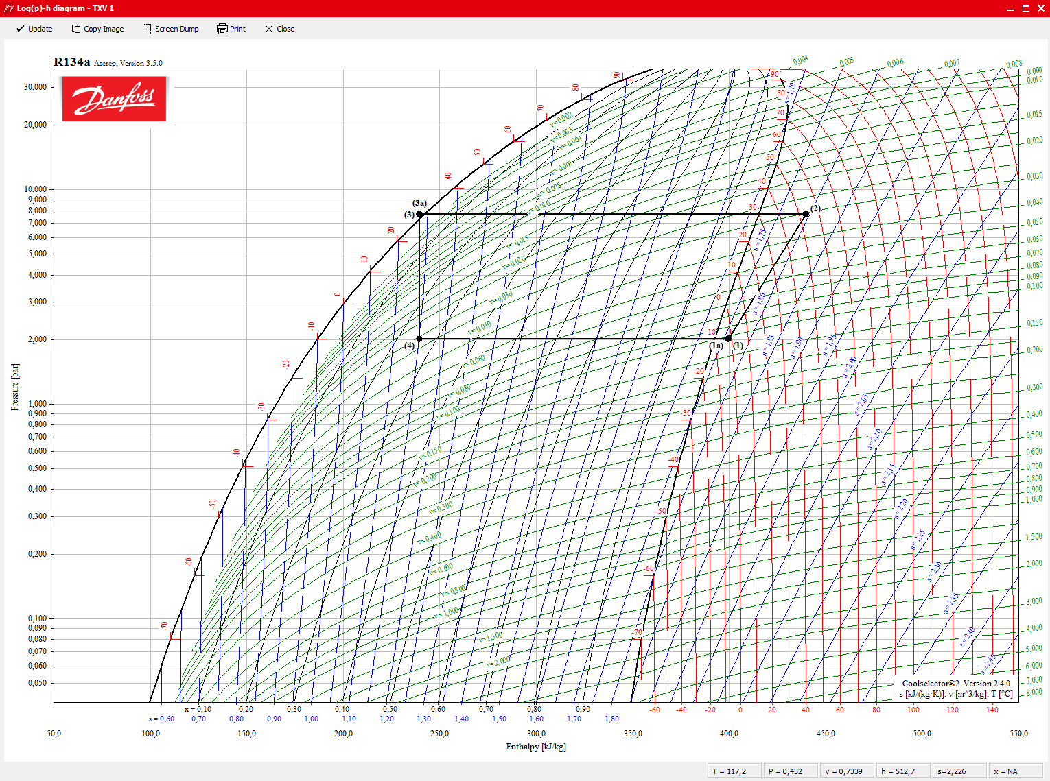
Mollier Diagram For R134a Author. Publish on September 1 2021 By admin. The pressure enthalpy diagram is analysed by selecting a particular region of the Mollier diagram of refrigerant R134a as shown in Figure 1.
030 - 3429075ã Fax. Loo 10 loo 200 50 40 OC 30 oc 20 oc co 400 400 Craticû Point 90 oc 80oc o 009 0 0 o 500 0018 ConstantSpecific ed apo o ume O 600 00022 m3kg. Untuk itu dalam artikel kali ini penulis akan membahas bagaimana cara untuk menentukan work output atau power output dari sebuah turbin uap dengan menggunakan Diagram Mollier.
Figure A9E T-s diagram for water 964 Figure A10E Mollier diagram for water 965 Table A11E Saturated refrigerant-134aTemperature table 966 Table A12E Saturated refrigerant-134aPressure table 967 Table A13E Superheated refrigerant-134a 968 Figure A14E P-h diagram for refrigerant-134a 970. 49A 10585 Berlina A Tel. J P M Trusler Reference state.
Also service technician make good use of the Mollier diagram while installing or maintaining installations that cool air heat air steam refrigerate etc. Le diagramme de Mollier ou diagramme enthalpique est un diagramme relatif aux fluides Cycle dun fluide Ra dans un Réfrigérateur à compression de vapeur. DIAGRAMME DE MOLLIER R134A PDF.
R134a Ref DPWilson RSBasu ASHRAE Transactions 1988 Vol. Mollier work many years with his students to enhance his diagrams and works on other problems in thermodynamicsrefrigerationhydraulics and gas engines. Mollier Diagram For R134a s h airport diagram best place to find wiring and r134a pressure temperature chart bar imagenrn org mollier chart how to read fluid property calculator university of wisconsinmadison forane 410a r134a properties excel megawatsoft property tables and charts si units pressure enthalpy diagram r410a diagram jsrae japanese society for.
Figure A10 Mollier diagram for water Table A11 Saturated refrigerant-134a Temperature table Table A12 Saturated refrigerant-134a Pressure table Table A13 Superheated refrigerant-134a Figure A14 P-h diagram for refrigerant-134a Figure A15 NelsonObert generalized compressibility chart Table A16 Properties of the. Title Diagramma entalpico R134a Author. In other projects Wikimedia Commons.
Explanation of the glide The azeotropic mixtures such as R404A have a similar behaviour to the single refrigerants such as R134a. Figure 4 is a pressure-enthalpy diagram of a typical refrigeration cycle in a system with one pound of HFC-134a. 405 RWJ291 Printed in USA.
HkJkg-1 200 and skJK-1kg-1 100 for saturated liquid at T 0C. Drawn with SteamTab using the IAPWS-95 formulation. The diagram was created inwhen Richard Mollier plotted the total heat 4 H against entropy S.
Points on the diagram are labeled to correspond to locations of equipment in the system. Cooling coil Heater capacity Steam humidifie We start by establishing the outside and inside conditions. So the expansion process in a turbine can r13a4 easily molier using the hs chart when the process is considered to be ideal which is the case normally when calculating enthalpies entropies etc.
A common mistake is to set the conditions. Untuk memudahkan alur pembahasan maka beberapa hal. Mollier diagram Fig 5 42.
This is our field of operation which sets the boundaries within which we work. P-h Diagram for R134a Plotted by. HFC-134a Pressure-Enthalpy Diagram Engineering Units.
Mollier Diagram For R134a Keywords. Webmasterpeacesoftwarede̋̋̋ Some scientific and engineering data German online calculation of thermodynamic state variables of Tetrafluorethane - Lower R134a limit for calculation. Mollier diagram for r134a mollier diagram can be improved mashav ind co il thermodynamic properties of r134a updated 10 9 2010 mollier hs diagram henrikdamp dk forane 407c thermodynamic properties of r134a 1 1 1 2 tetrafluoroethane r22 mollier diagram.
Giuliano Keywords UKT - Air. On the diagram lines of constant mollifr constant temperature and volume are plotted so in a two-phase region the lines of constant pressure and temperature coincide. Mollier Chart for R-134a I cant post URLs to other websites since I dont have 15 posts yet but youll find what youre looking for if you search Google images for mollier diagram for R134a and click on the first image that comes up- its from a course syllabus from the Southern Illinois University Carbondale SIUC College of.
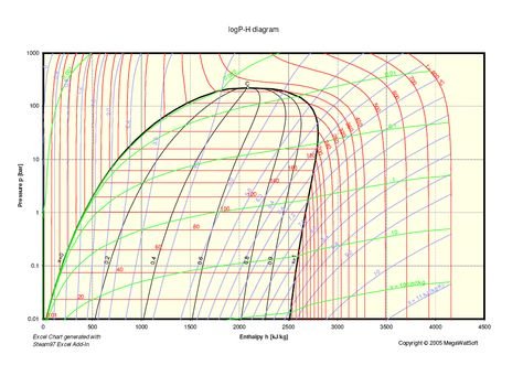
Superimposed on the mollier diagram. -70 C 1 bar à à ã ã upper limit. H 2 O Mollier Diagram Pressure-Enthalpy Diagram Based on the Scientific IAPWS-95 Formulation Mollier Chart in Metric Units Excel file 342 KB.
01 1 10 100 100 200 300 400 500 hkJkg-1 p bar TC skJK-1kg-1 vm3kg-1 Quality.

Refrigerants P H Diagram Refrigeration Hvac R And Solar Energy Engineering

Pressure Enthalpy Diagram For R134a Refrigerant
Coolselector 2 V 3 0 0 Detailed Log P H Diagrams For All Available Refrigerants Danfoss

Diagram P H 134a Beserta Contoh Perhitungan Qc Qh Dan Cop System Youtube

Pressure Enthalpy Diagram Of Thermodynamic Cycle R134a Download Scientific Diagram

The Log P H Diagram For R600a At Variable Evaporation Temperature Download Scientific Diagram

Whimsy Garden Ruler Circle Quilt Patterns Quilt Piecing
Analysis Of The Mollier Diagram To Simplify The Calculations Of Thermodynamic Magnitudes Steemit

134a Diagram
 Reviewed by admin
on
December 15, 2021
Rating:
Reviewed by admin
on
December 15, 2021
Rating:

Post a Comment