
Mollier Diagram Turbine
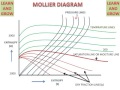
Commonly used Mollier diagrams are the enthalpy-entropy or h-s diagram below and the pressure-enthalpy diagram illustrated at the bottom of this page. We will find that the h-s diagram is extremely useful for evaluating adiabatic turbines and compressors and complements the P-h diagram which we used in Chapter 4 to evaluate entire steam power plants.

Diagram Mollier For Boiler And Turbine How To Calculation Alwepo
Your consideration of Mollier diagrams in this course will be limited to a qualitative look at the turbine set.
Mollier diagram turbine. The turbine flows out of the steam piping at medium or low pressure. The available energy that can be converted into work is shown on the Mollier diagram as a vertical line hc hd. Turbine work out Pump work hc hd hb ha Heat i.
The Mollier diagram is a tool used by engineers to predict theoretically the performance of systems and installations. The expansion process is customarily calculated manually on sh graphs such as the Mollier diagram. Mollier Diagrams The Mollier diagram is a very useful tool.
Notice that to trace the real expansion line a turbine efficiency must be assumed here Fig. It can be used to depict the various processes associated with the tur bine set. Steam expansion in the turbine on the h-s Mollier chart You can switch back to the summary page for this application by clicking here.
The difference in enthalpy H 2-H 2 is called the reheat factor and is the basis for multi-stage turbines. A typical chart covers a pressure range of 0011000 bar and temperatures up to 800 degrees Celsius. The h-s diagram is one in which Enthalpy.
The Mollier diagram also called the enthalpy h entropy s chart or h-s chart is a graphical representation of thermodynamic properties of materials. More recently property packages have been developed that allow the calculation of a full expansion line on a personal computer. The Mollier diagram is useful when analyzing the performance of adiabatic steady-flow processes such as flow in nozzles diffusers turbines and compressors.
Ideal simple Rankine cycle thermal efficiency is represented by. Superheated 600-psig steam at 700F Point 1 expands as it passes through the turbine and is exhausted at a. Note the efficiency andor power can also be calculated manually using a steam Mollier chart and steam tables such as Keenan and Keyes.
A Mollier diagram for water is. The fluid velocities at entry to and exit from a turbine may be quite high and the corresponding kinetic energies significant. Turbine expansion process on the H-S Mollier diagram drawn using SteamTab 40.
Turbine work out hc hd Heat in. Line 12 represents the actual expansion and line 12 s the ideal or reversible expansion. It shows enthalpy in terms of internal energy pressure and volume using the relationship or in terms of.
Point 1 Turbine Inlet Point 2 LP exhaust for process heating Point 3 Exhaust to CW condenser. Mollier diagrams are graphical representations of the thermodynamic properties of materials involving Enthalpy as one of the. MATHEMATICAL MODEL The following figure 5 is an enthalpy-entropy diagram Mollier diagram 3 of the expansion process for a radial turbine with a diffuser where 1 2 3 and 4 represent the entry to the stator entry to the rotor exit from the rotor and exit.
90o IFR turbine arrangement and velocity triangles II. Figure 19a shows a Mollier diagram representing the expansion process through an adiabatic turbine. Pump work is often left out of this equation and thus.
This video session is made to make the students conversant with basic concepts of Turbo MachinesI acknowledge my sincere thanks to the authors and referenc. Pertaining to turbine expansion process the mollier diagram aids in visualizing the isentropic and real expansion processes as well as the. An enthalpyentropy chart also known as the HS chart or Mollier diagram plots the total heat against entropy describing the enthalpy of a thermodynamic system.
Willard Gibbs suggested using a surface with entropy pressure and total heat as co-ordinates. As can be seen on the Mollier diagram the pressure curves are divergent. Download and print Mollier Diagram for Water - Steam.
The term Mollier diagram named after Richard Mollier 1863-1935 refers to any diagram that features Enthalpy on one of the coordinates. Turbine Effective Cycle Chemistry Control steamcycle com April 29th 2018 - Entropy Btu lb OF No Non reheat 20 ppb NaC1 10 ppb NaOH 10 ppb ppb Entropy Btu lb OF Figure 13 Mollier diagram for reheat and non reheat turbine steam expansion. Velocity diagram The Mollier diagram is a plot of enthalpy against entropy for a process in which one property usually pressure or temperature is kept constant 4.
There are two property diagrams involving entropy in common usage the temperature-entropy T-s and enthalpy-entropy h-s Mollier diagrams. This video tutorial for SESM2011-Thermodynamics covers how to use steam tables and the Mollier chart by looking at the specific example of finding the enthal. Such diagrams find use in design include steam turbines refrigeration weather forecasting and air drying systems for the food sucks as coldstores and.
In general it is a relationship between enthalpy measure of the. Basically the exhaust steam can be used effectively. The Mollier Chart also called enthalpy entropie chart the h-s chart or called the psychrometric chart is a chart devised by Richard Mollier in 1904 that expands the enthalpy against entropy.
The diagram below can be used to determine enthalpy versus entropy of water and steam. This process can be followed on an enthalpy-entropy H-S diagram known as a Mollier chart. The Mollier diagram is a projection of this surface on the pressure plane and thus has entropy and total heat as co-ordinates.
The temperature-entropy diagram is much inferior to the Mollier diagram for the quantitative solution of problems in steam-turbine design. In the example diagram the path from Point 1 to Point 2 represents typical BPST operation at a chemical plant pulp and paper mill oil refinery or food processing facility. 584 BulletinoftheBureauofStandards Voi7No4 channelsowellprotectedthattheheatleakageisnegligibleIn thecaseofaproperlydesignedvelocity-compoundedimpulse turbine.
Shaft power necessary for non-condensing or condensing turbines with wet exhaust steam See Figure 1 for typical units used for the calculations. The internal turbine efficiency is therefore given by. HEAT THE MOLLIER DIAGRAM IS THE EUROPEAN VERSION OF THE ANGLO AMERICAN OF THIS STEAM BY TEN DEGREES REQUIRES 10 X 0 h x diagram mollier ja soft com october 16th 2018 - h x diagram mollier pre adjustments can be made in the following ranges air pressure from 100 to 10 000 mbar temperature rom 50 c to 80 c Help CO2 Properties Calculator.
It may also be used quantitatively for various calculations.

Turbine Expansion Process On The H S Mollier Diagram Drawn Using Download Scientific Diagram
Typical Pwr Steam Path In The Mollier Diagram Simplified Schematic Hp Download Scientific Diagram

Mollier Chart How To Read Youtube
Mollier Diagram

Section Of Mollier Chart Showing Expansion Line Download Scientific Diagram

Mollier Diagram Of The Full Turbine Stage Download Scientific Diagram

File Steam Turbine Cycle Png Wikimedia Commons

Inside Power Station Mollier Chart

Diagram Mollier For Boiler And Turbine How To Calculation Noakmech

Mollier Diagram An Overview Sciencedirect Topics

Turbine Expansion Process On The H S Mollier Diagram Drawn Using Download Scientific Diagram

Diagram Mollier For Boiler And Turbine How To Calculation Alwepo

Supercritical Steam Power Plant For Athens Ohio Updated 2 20 11

Mollier Diagram An Overview Sciencedirect Topics
 Reviewed by admin
on
December 08, 2021
Rating:
Reviewed by admin
on
December 08, 2021
Rating:

Post a Comment