
Er Diagram Does Not Represent Conceptual Level Of A Database System
Then you dont have to switch modeling conventions in mid stream. The nature of these relationships can be quickly and easily shown by.

Database Modeling Entity Relationship Diagram Erd Part 5 By Omar Elgabry Omarelgabry S Blog Medium
Many experts dont follow my practice.

Er diagram does not represent conceptual level of a database system. The authors present a new method for creating a graph database schema GDBS based on an entity-relationship diagram ERD of the application domain which is. This ER diagram is used to represent the relation and data elements. We also show how the establishment of standard types of functional entity motivates practical guidelines for the conversion of the design to the implementation level.
It is used to analyze to structure of the Database. Entity-Relationship ER Model 4. Lastly ER diagrams may be applied in other contexts such as describing the different.
CREATE TABLE Managesssn CHAR11 did INTEGER. The ER diagram represents the conceptual level of database design meanwhile the relational schema is the logical level for the database design. Context Design Implementation Process 2.
ER diagram is widely used in database design. Entities are represented by. It develops a conceptual design for the database.
It helps us to visualize our database and gives us a conceptual view for it also makes it easy to understand at high level. If a database system is processing three queries as part of a transaction and the third query fails what happens to the transaction. An ER schema can be represented by a collection of tables which represent contents of the database instance.
What are the fundamentals required for understanding and designing ER diagrams. It works around real-world entities and the associations among them. For example Suppose we design a school database.
Although it is constructed in such a way as to allow easy translation to the relational schema model this is not an entirely trivial process. Entity Relationship Diagram also known as ERD ER Diagram or ER model is a type of structural diagram for use in database design. Entities Attributes Relationships CS275 Fall 2010 2 Entities Refers to entity set and not to single entity occurrence Corresponds to table and not to row in relational environment.
Separate tables for Employees and Departments. ER diagram of Bank has the following description. Since each department has a unique manager we could instead combine Manages and Departments.
This model is used to define the data elements and relationship for a specified system. With the help of this we can easily represent our database as a simple diagram which is called an entity-relationship diagram. Note that did is the key now.
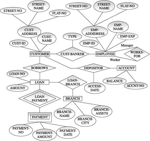
ER diagram of Bank Management System. Let us now learn how the ER Model is represented by means of an ER diagram. Any object for example entities attributes of an entity relationship sets and attributes of relationship sets can be represented with the help of an ER diagram.
The major entities within the system scope and the inter-relationships among these entities. Entities attributes and relationships. It also develops a very simple and easy to design view of data.
An ERD contains different symbols and connectors that visualize two important information. Describe things and their relationships in high level. They opine that the ER model is superfluous for conceptual modeling and that its best to begin with a relational model at the conceptual level while you are still doing the requirements analysis.
At view level the ER model is considered a good option for designing databases. ER Diagram stands for Entity Relationship Diagram also known as ERD is a diagram that displays the relationship of entity sets stored in a database. Database Management Systems R.
An entity can be a real-world object either animate or inanimate that can be easily identifiable. Primary keys allow entity types and relationship types to be. CS3200 Database Design Spring 2018 Derbinsky Outline 1.
ER diagrams are created based on three basic concepts. From a theoretical point of view they are right. Diagrams created to design these entities and relationships are called entityrelationship diagrams or ER diagrams.
Relationship Diagram FERD which can be used for high level conceptual modelling of heterogeneous KM systems and illustrate its use with a case study. The successful query results are reversed and the transaction is. In this database the.
In ER modeling the database structure is portrayed as a diagram called an entity-relationship diagram. The ER Model is intended as a description of real-world entities. ER Diagrams contain different symbols that use.
Entity-relationship models are one of the most popular ways to create a quick and clear conceptual data model. Goals of Conceptual Design 3. An ER model provides a means of communication.
Ramakrishnan 7 Translating ER Diagrams with Key Constraints Map relationship to a table. ER diagram is known as Entity-Relationship diagram. Represent conceptual level of a database system.
ER model forms the basis of an ER diagram ERD represents conceptual database as viewed by end user ERDs depict databases main components. An ER model consists of entities attributes and relationships. It shows relationships between entities and their attributes.
In addition ER diagrams can directly be used by database developers as the blueprint for implementing data in specific software applications. The ER model defines the conceptual view of a database. In other words ER diagrams help to explain the logical structure of databases.

Catalogue Database Conceptual Er Model Download Scientific Diagram
Which One Is Er Diagram Stack Overflow
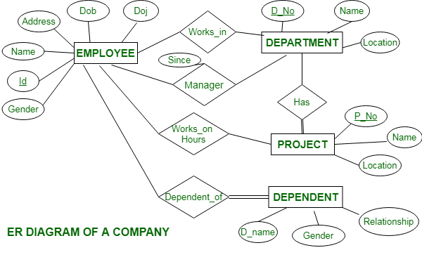
Er Diagram Of A Company Geeksforgeeks

Standard Flowchart Symbols And Their Usage Basic Flowchart Symbols And Meaning Workflow Di Relationship Diagram Workflow Diagram Electrical Circuit Diagram

The Entity Relationship Diagram For The Movie Recommendation System Download Scientific Diagram
E R Diagram Symbols Database Systems Concepts Design And Applications Book
3 Entity Relationship Diagram For The Airline Example Download Scientific Diagram
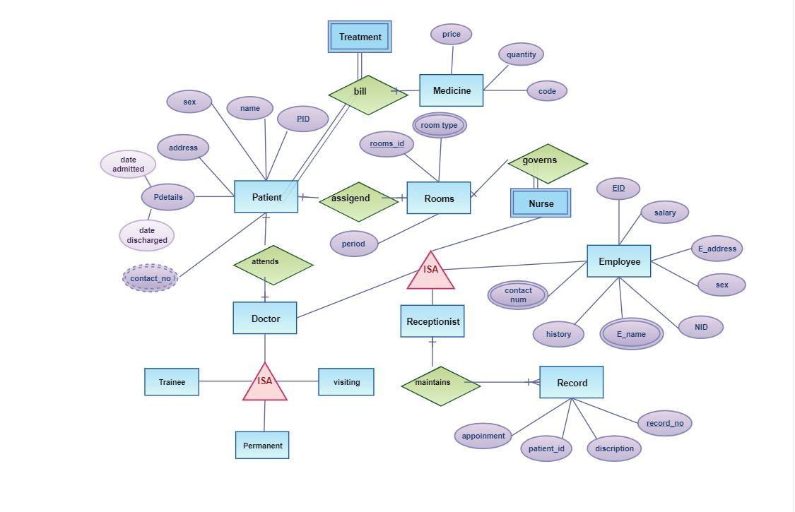
Solved Given Below Is An Er Diagram Of The Hospital Chegg Com

The Entity Relationship Diagram Of Online Movie Ticket Booking System Shows All The Visual Elements Of Database Relationship Diagram Diagram Door Design Images

Post a Comment