
Er Diagram Practice Problems
ER Model stands for Entity Relationship Model is a high-level conceptual data model diagram. Please identify an attribute in the above ER diagram that might represent a composite attribute and explain whyhow it might represent a composite attribute 3 pts.

Entity Relationship Diagram Download Scientific Diagram
The Child has no NRIC attribute.

Er diagram practice problems. You can find this diagram at no cost. Previous Year GATE Questions Based on ER Diagram. Attributes are the properties which define the entity type.
The line on the arrow to the attribute Given_name indicates this attribute together with the identifier of Employee ie. Plus with GitMind you will be able to create a bunch of diagrams for visualizing the data or processes of a system. November 5 Ross closing time Name.
Solve company interview questions and improve your coding intellect. An Entity is an object of Entity Type and set of all entities is called as entity set. Many of the attributes could actually represent composite attributes.
B Branch No of the Bank-Branch entity is a partial Key. If you wish to have this diagram click the image immediately and do as the actual way it clarifies in the photo. If you would like have this diagram click the image without delay and do as the way it describes in the snapshot.
Since you have an idea about the ER notations examples and guidelines you should be able to draw this diagram with ease. ER diagrams also are often used in conjunction with data flow diagrams DFDs which map out the flow of information for processes or systems. A Bank-Branch is the weak entity.
ER diagrams constitute a very useful framework for creating and manipulating databases. The rules used for converting an ER diagram into the tables are already discussed. For Problem 4 you should attach extra pages as needed.
Basic ER Diagram template Click to use as template Benefits of ER diagrams. Peter Pin-Shan Chen currently a faculty member at Carnegie-Mellon University in Pittsburgh is credited with developing ER modeling for database design in the 1970s. For example Roll_No Name DOB Age.
This ER diagram shows the relationship named Study In between two entities Student and College. Medium 150x150 large 640x640 Er Diagram Practice Problems With Solutions This is amongst the types of ER Diagram. Have the ER diagram now.
The rules used for converting an ER diagram into the tables are already discussed. In the design we want to capture the following. What are the differences between this ER diagram and the previous pages ER diagram.
Finally export the ERD diagram example to an image or PDF file. Nouns give rise to entity type names Verbs indicate names of relationship types Choose binary relationship names to make ER diagram readable from left to right and from top to bottom Review all attributes. In this article we will discuss practice problems based on converting ER Diagrams to Tables.
An ER Diagrams Building Blocks. Create an Entity-Relationship ER model is to visually represent the structure of a business database where data equates to entities or objects that are linked by defined relationships expressing dependencies and requirements. The NHL has many teams each team has a name a city a coach a captain and a set of players each player belongs to only one team.
E1 is an entity having Entity Type Student and set of all students is called Entity Set. APPROPRIATE ER MODEL DESIGN Choose names that convey meanings attached to various constructs. Entity-Relationship Diagram ERD solution extends ConceptDraw PRO software with templates samples and libraries of vector stencils from drawing the ER-diagrams by Chens and crows foot notations.
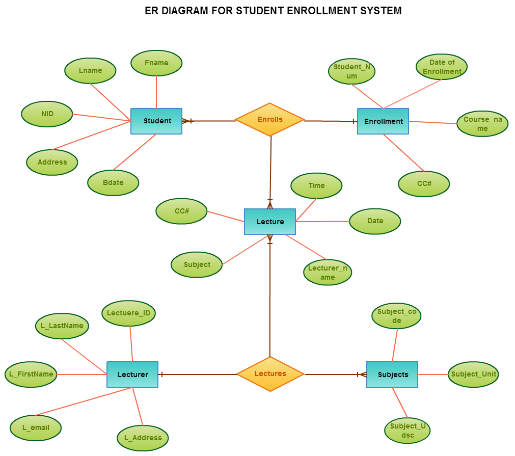
Student entity has three attributes Stud_id Stud name Stud addr which are represents its corresponding properties of Studen entity. ER diagram of hospital management system. ER Diagram or ERD is short for Entity Relationship Diagram.
E form the identifier of the weak entity type Child. CS3200 Database Design Spring 2018 Derbinsky Outline 1. Entity-Relationship ER Diagrams Lecture 7 February 11 2018 Entity-Relationship ER Diagrams 1.
Solution of Exercise 1. This is a many to many relationship. C The Participation of BANK in BRANCHES Relationship is partial.
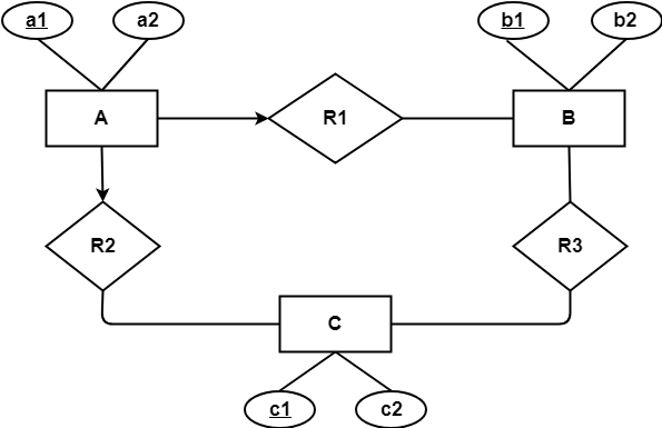
Which is the correct statement regarding the above diagram. First ER diagrams are easy to understand and do not require a person to undergo extensive training to be able to work with it efficiently and accurately. The ER Model represents real-world entities and the relationships between them.
This is because relational models can be easily implemented by RDBMS like MySQL Oracle etc. This is because relational models can be easily implemented by RDBMS like MySQL Oracle etc. In this article we will discuss practice problems based on converting ER Diagrams to Tables.
ER diagram is converted into the tables in relational model. Erd Sample Problems With Solutions. Please Like Subscribe if you want more CS Tutorials.
ER model helps to systematically analyze data requirements to produce a well-designed database. History of ER models Peter Chen aka. ER diagram is converted into the tables in relational model.
Er Diagram Practice Problems With Solutions This is amongst the samples of ER Diagram. Platform to practice programming problems. Entity or relationship attributes.
TERnary Relationship In ER Diagram Examples. We have a set of teams each team has an ID unique identifier name main stadium and to which city this team belongs. Practice ER Diagram Question A Sample Solution Suppose you are given the following requirements for a simple database for the National Hockey League NHL.
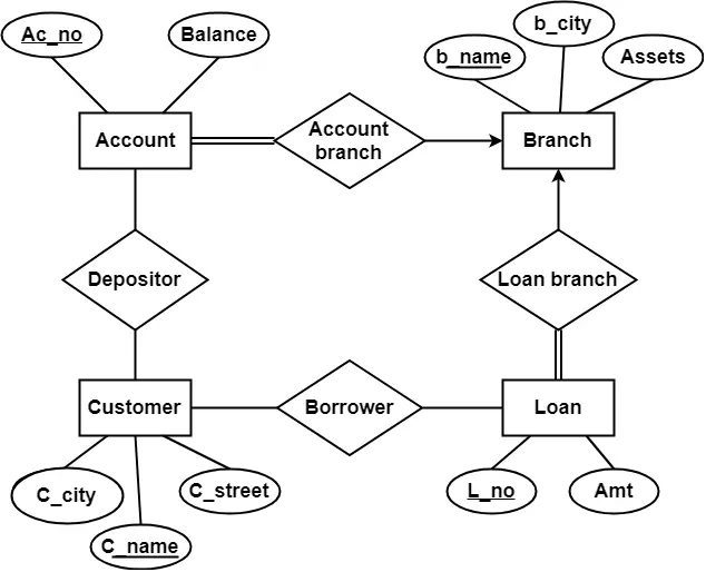
ER Diagram Example 1. Consider an ER diagram given below for Bank database. The first element of the ER.
Assume we have the following application that models soccer teams the games they play and the players in each team. Creating an ER Model in DBMS is considered as a best practice before. The following questions refer back to the above ER diagram for problem 3.
You can find this diagram at no cost. It maps out the problem to be modeled but in a structured way that shows the relationships between entities. Print out this exercise and answer the questions on the printout.
By nature it is an abstract visualization the first step in the design process towards creating a logical and functional database. ER diagrams consist of the following elements. In ER diagram Entity Type is represented as.
Entity Relationship Diagram Erd Er Diagram Tutorial Relationship Diagram Exam Diagram

Specialization Top Down And Generalization Bottom Up Approach Entity Relationship Example Relationship Diagram Tutorial Diagram

Developing An Application Relationship Diagram Learn Programming Purchase Order Template

E R Diagram Of Shopping Site Like Flipkart Practice Geeksforgeeks Relationship Diagram Shopping Sites Diagram
2
Entity Relationship Diagram Erd Er Diagram Tutorial
Er Diagrams To Tables Practice Problems Gate Vidyalay
Er Diagrams To Tables Practice Problems Gate Vidyalay

Entity Relationship Diagram Erd Er Diagram Tutorial Relationship Diagram Diagram Website Design

Post a Comment