
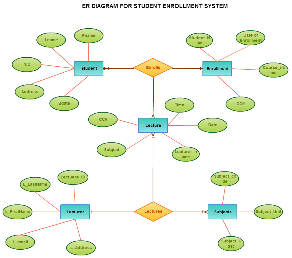
Er Diagram 2 Lines
An ER diagram can express the overall __________of a database graphically. A dashed line means that the relationship is strong whereas a solid line means that the relationship is weak.

Entity Relationship Diagram Staruml Documentation
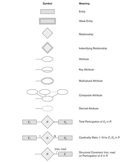
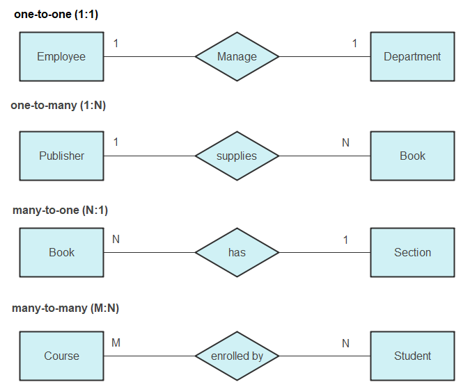
Replaces cardinality ratio numerals and singledouble line notation Associate a pair of integer numbers min max with each participation of an entity type E in a relationship type R where 0 min max and.

Er diagram 2 lines. Entities attributes and relationships. ER diagrams are created based on three basic concepts. Click to see full answer.
What is ER Diagram. Includes some constraints but not operations. Different shapes at the ends of these lines represent the cardinality of the relationship.
They are weak entity multi valued attribute derived attribute weak relationship and recursive relationship. Lucidchart is the leading ER diagram tool. And also employee entity holds the attribute such as role salary emp_id.
For more information contact your Microsoft 365 admin. Crows foot notation is used in Barkers Notation Structured Systems Analysis and Design Method SSADM and information engineering. Ketiga hal tersebut dapat membantu memvisualisasikan bagaimana data saling terhubung dan berguna untuk mengonstruksi basis data relasional.
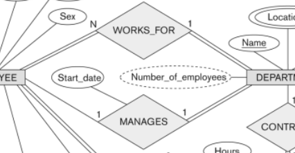
On the following diagram how do we decide that the relationship between the Room and Class entities is strong. Let us now learn how the ER Model is represented by means of an ER diagram. It is an example of a recursive relationship in an ER diagram.
ERD diagrams are commonly used in conjunction with a data flow diagram to display the contents of a data store. The Rectangles divided into two parts represents. Saat kamu ingin mulai membuat ERD ada beberapa istilah umum dan komponen ERD yang perlu.
If your admin has turned on self-service purchasing you can buy a license for Visio yourself. 2 Purpose of ER Model The ER model allows us to sketch database schema designs. Creating and editing entity relationship diagrams on Visio for the web requires a Visio Plan 1 or Visio Plan 2 license which is purchased separately from Microsoft 365.
In other words ER diagrams help to explain the logical structure of databases. It contains an ER Diagram which is crucial for. There are several ER diagram notations exist and only differ a little.
When documenting a system or process looking at the system in multiple ways increases the understanding of that system. They help us to visualize how data is connected in a general way and are particularly useful for constructing a relational. An entity set is a group of similar entities and these entities can have attributes.
In ER diagram key attribute is represented by an oval with underlying lines. Today we will be briefly discussing them and their notation styles. In ER diagram attribute is represented by an oval.
Diagram ER biasanya berhubungan langsung dengan diagram data flow untuk menampilkan konten data store. Use Createlys easy online diagram editor to edit this diagram collaborate with others and export results to multiple image formats. ER Diagram for Online Shopping System.
There are more elements which are based on the main elements. You can edit this template and create your own diagram. You have to be certain of course that the relationships capture different information and that you havent say mistaken the two aspects of a single relationship as two.
ER Diagram stands for Entity Relationship Diagram also known as ERD is a diagram that displays the relationship of entity sets stored in a database. There is no reason you cant have multiple relationships between the same two entities your understanding is wrong in this respect. Elements in ER diagrams.
There are three basic elements in an ER Diagram. An ER diagram shows the relationship among entity sets. Convert ER designs to relational DB designs.
ER diagrams Diagrammatic notation associated with the ER model 2. This relationship has two roles such as employee and manager with the employee entity. Below are pre-drawn ER diagram symbols in Edraw ER diagram software including entity weak entity strong relationship weak relationship attribute derived attribute constraint and participation etc.
Designs are pictures called entity-relationship diagrams. This guide will help you to become an expert in ER diagram notation and you will be well on your way to model your own database. The entity-relationship model is a speculation of these models.
Entity-relationship diagrams ERD are essential to modeling anything from simple to complex databases but the shapes and notations used can be very confusing. What is dotted line in ER diagram. The entity relationship set is represented in E-R diagram as.
Database Management System Entity Relationship diagram MCQs. Cardinality and ordinality are two other notations used in ER. Entityrelationship modeling was developed for.
The major entities within the system scope and the inter-relationships among these entities. Show activity on this post. Key Attribute The attribute which uniquely identifies each entity in the entity set is called key attributeFor example Roll_No will be unique for each student.
Dashed lines link attributes of a relationship set to the relationship set. The entity-relationship ER data model is created out of the activity of utilizing commercially accessible DBMS to model application database. Crows foot diagrams represent entities as boxes and relationships as lines between the boxes.
ER Diagram Example 4. Creately diagrams can be exported and added to Word PPT powerpoint Excel Visio or any other document. In terms of DBMS an entity is a table or attribute of a table in database so by showing relationship among tables and their attributes ER diagram shows the complete logical structure of a database.
In software engineering an ER model is commonly formed to represent things a business needs to remember in order to perform business processesConsequently the ER model becomes an abstract data model that defines a data or information structure which can be implemented in a database typically a relational database. That is an Employee entity is recursively related to itself by the relationship of works_for. The Chens ERD notation is still used and is considered to.
This set of Advanced Database Management System focuses on Entity Relationship Diagram MCQs Multiple Choice Questions and Answers. Any object for example entities attributes of an entity relationship sets and attributes of relationship sets can be represented with the help of an ER diagram. The first part of the rectangle contains the name of the entity set.
ER diagrams are used to model and design relational databases in terms of logic and business rules in a logical data model and in terms of the specific technology to be implemented in a physical data model In software engineering an ER diagram is often an initial step in determining requirements for an information systems project. Entity Relationship Diagram also known as ERD ER Diagram or ER model is a type of structural diagram for use in database design. An ERD contains different symbols and connectors that visualize two important information.
Database Modeling Entity Relationship Diagram Erd Part 5 By Omar Elgabry Omarelgabry S Blog Medium
Entity Relationship Diagram Erd Er Diagram Tutorial
Database Modeling Entity Relationship Diagram Erd Part 5 By Omar Elgabry Omarelgabry S Blog Medium
7 Tips For A Good Er Diagram Layout Vertabelo Database Modeler
3 Entity Relationship Diagram For The Airline Example Download Scientific Diagram
Entity Relationship Diagram Erd Er Diagram Tutorial
Er Diagram Symbols And Notations Edraw
Vertabelo Feature How To Organize Your Erd Diagram In Vertabelo Vertabelo Database Modeler

What Does The Dashed Line Mean Under The Booktitle Attribute Of The Book Entity Stack Overflow

Post a Comment