Er Diagram Double Circle
Physical ER models show all table structures including column name column data type column constraints primary key foreign key and relationships between tables. The most popular notation in ER diagrams is the Information Engineering IE notation also called crows foot notation.
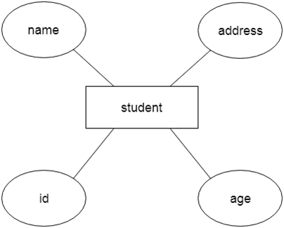
Dbms Er Model Concept Javatpoint
Gambar di atas merupakan transition diagram DFA.

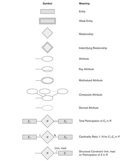
Er diagram double circle. The foreign key is typically a primary key of an entity it is related to. Square - Entity name Circle - Simple attribute Double Circle - Multi-valued attribute ie array Dotted circle - Derived attribute uses other attributes Composite attributes are drawn like a subtree. The staff the collection is all of those Janitor Person instances.
Since ER diagram is the pictorial representation of real world objects it involves various symbols and notation to draw the diagrams. In relational database design a one-to-one 11 relationship exists when zero or one instance of entity A can be associated with zero or one instance of entity B and zero or one instance of entity B can be associated with zero or one instance of entity A. A _____ attribute is an attribute whose values can be calculated from related attribute values.
Physical ER diagram symbols The physical data model is the most granular level of entity-relationship diagrams and represents the process of adding information to the database. This however is more like a kind of category. This is the default ER diagram notation used in Vertabelo.
Switch is a device for making and breaking the connection in an electric circuit. Any object for example entities attributes of an entity relationship sets and attributes of relationship sets can be represented with the help of an ER diagram. Rectangles are used to represent the entity in the diagram.
In a state diagram the starting state is denoted by a circle with an incoming arrow and an accepting state is denoted by a double circle. The dotted circle is. Each circle represents the state.
Well discuss them in. The transition diagram is also called a transition graph. A state diagram has only one starting state.
Let us see one by one below. Transition diagram circle merepresentasikan state double circle merepresentasikan final state q0 sampai q2 merupakan nama state arrow dari α ke β dengan label γ merepresentasikan fungsi transisi δα γ yang menerima parameter state α dan input symbol γ lalu mengembalikan state β sebagai hasilnya. The double circle is a _____ attribute.
The ER diagram was created by. Double circle indicates the final state or accepting state. In ER diagrams the existence dependency is shown by.
The initial state in the transition diagram is marked with an arrow. In entity relationship diagrams ER diagrams a weak entity set is indicated by a bold or double-lined rectangle the entity connected by a bold or double-lined type arrow to a bold or double-lined diamond the relationship Weak entity. When it comes to disjoint or overlap of entities the topic becomes about a super class and a subclass.
It is represented by a diagraph. E-ER diagram shows specialization circle IsA relationship and inheritance symbol subset symbol Specialization can also involve just one subclass no need for circle but show inheritance symbol The sub-entities are most likely invoking the disjointedness constraint. Electrical isolators separate a part of the system from rest for safe maintenance works.
Enhanced ER or EER diagrams Diagrammatic technique for displaying these concepts in an EER schema Subtype or subclass of an entity type Subgroupings of entities that are meaningful Represented explicitly because of their significance to the database application. SPST is a single-pole single-throw SPST switch. Let us now learn how the ER Model is represented by means of an ER diagram.
For example if an organization has an owner and if the owner can be a person a company or a bank then it is a union of entities if they are separate tables. Isolator is a mechanical switch that isolates a part of a circuit from the system as when required. A single occurrence of an entity type is known as an entity _____.
The total participation by entities is represented in E-R diagram as -- Dashed line -- Double line -- Double rectangle -- Circle Miscellaneous or General Database Systems. An ER model is a diagram containing entities or items relationships among them and attributes of the entities and the relationships. ER Diagrams are most often used to design or debug relational databases in the fields of software engineering business information systems education and research.
Definition The Entity-Relationship ER model a high-level data model that is useful in developing a conceptual design for a database. Entity Sets describe the type of an entity. Entities are represented by.
An entity-relationship ER diagram is created based on these three types which are listed below. There are a few standard symbols used in logical and physical ER diagrams and some useful additional non-standard symbols that you can use in Vertabelo. An Entity Relationship ER Diagram is a type of flowchart that illustrates how entities such as people objects or concepts relate to each other within a system.
In ER-diagrams a multi-valued attribute is shown by a ____. An object a component of data is known as an _____ instance. So the wordconcept of staff need not appear.
Usually a double circle means. The circle is another symbol for IsA. A transition graph consists of three things.
SPDT is single-pole double-throw SPDT switch. Double Line Circle In E R Diagram What Represents. Double circle Role names may be used when two entity types are associated through more than one ____ type.
There can be more than one accepting states or no accepting states. The example Design elements - ER diagram Chen notation is included in the Entity-Relationship Diagram ERD solution from the Software Development area of ConceptDraw Solution Park. A better name for that entitytable might be Janitor or Janitor Person with a double-circle noting that you can have more than one staff person.
An identi er can be de ned as a string of letters and digits that begins with a. Name of the Entity is. You may be conflating the collection of staff with the notion of individual persons.
ER Modelling is another way to describe the relationship between data objects.

Entity Relationship Diagram Erd Er Diagram Tutorial College Management Relationship Diagram Tutorial

Er Diagram For Pharmacy Relationship Diagram Software Design Patterns Programming Patterns
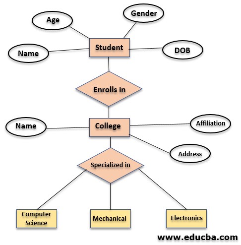
Entity Relationship Model Complete Guide To Entity Relationship Model
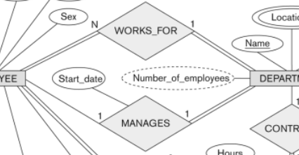
Database Modeling Entity Relationship Diagram Erd Part 5 By Omar Elgabry Omarelgabry S Blog Medium

Entity Relationship Diagram Erd Er Diagram Tutorial

Database Modeling Entity Relationship Diagram Erd Part 5 By Omar Elgabry Omarelgabry S Blog Medium
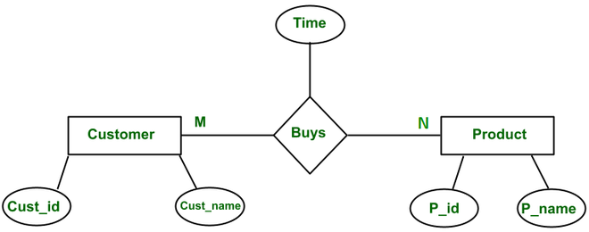
What Is Mapping Cardinalities Er Diagrams Geeksforgeeks

Entity Relationship Diagram Erd Er Diagram Tutorial
Database Modeling Entity Relationship Diagram Erd Part 5 By Omar Elgabry Omarelgabry S Blog Medium

Post a Comment