P Diagram In Fmea
So what is a P-Diagram. Process Flow Diagram is the.

Fmea Corner Parameter Diagrams P Diagrams
Hi guys Google to the rescue as usual a P-Diagram is a Parameter diagram.

P diagram in fmea. In 2020 the AIAG VDA FMEA Handbook also presented this tool and proposed a variant. Berikut beberapa hasil penggunaan Ishikawa diagram yang ditampilkan dalam Tabel 2. Header light green and columns light blue.
System elements und their functions aredescribedandvisualizedin a simplistic manner. The Parameter Diagram P-Diagram is ablock diagramwhich shows the connections between differentparameters of a system. These pieces of information are normally necessary for quality management.
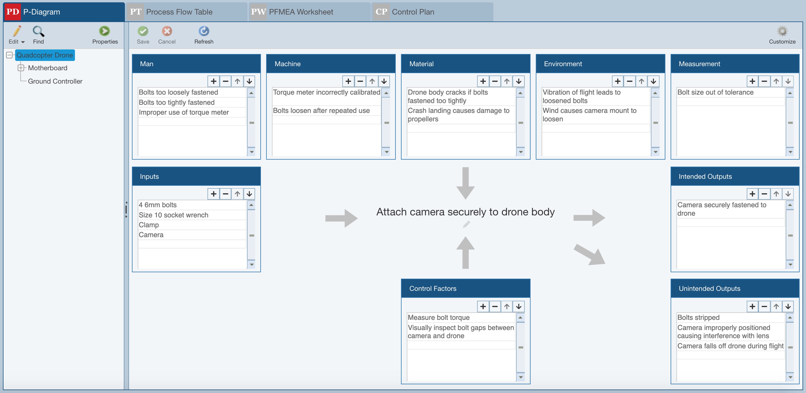
Foundation The process must be defined step by step including interfaces The PFD provides the structure to document what product characteristics and requirements OUTPUTS are affected by a given operation and how these characteristics and sources of variation are controlled INPUTS. P-Diagrams Parameter Diagrams provide another layer to PFMEAs that can be used for upfront assessment that your required process outputs are met considering all inputs. Relyence P-Diagrams usage is optional and they can be customized to meet your needs.
In addition to the ideal functions produced by the item the P-Diagram captures the. Causes at the system level are cascaded as failure modes in more detailed analysis. P-diagram in FMEA preparation - What does the P stand for in P-diagram.
If there are design inputs or special characteristics the effect on end user is also included. Anticipation of Potential Problems. P-Diagrams are part of the preparation work done before you actually start to complete the Design or Process FMEA form.
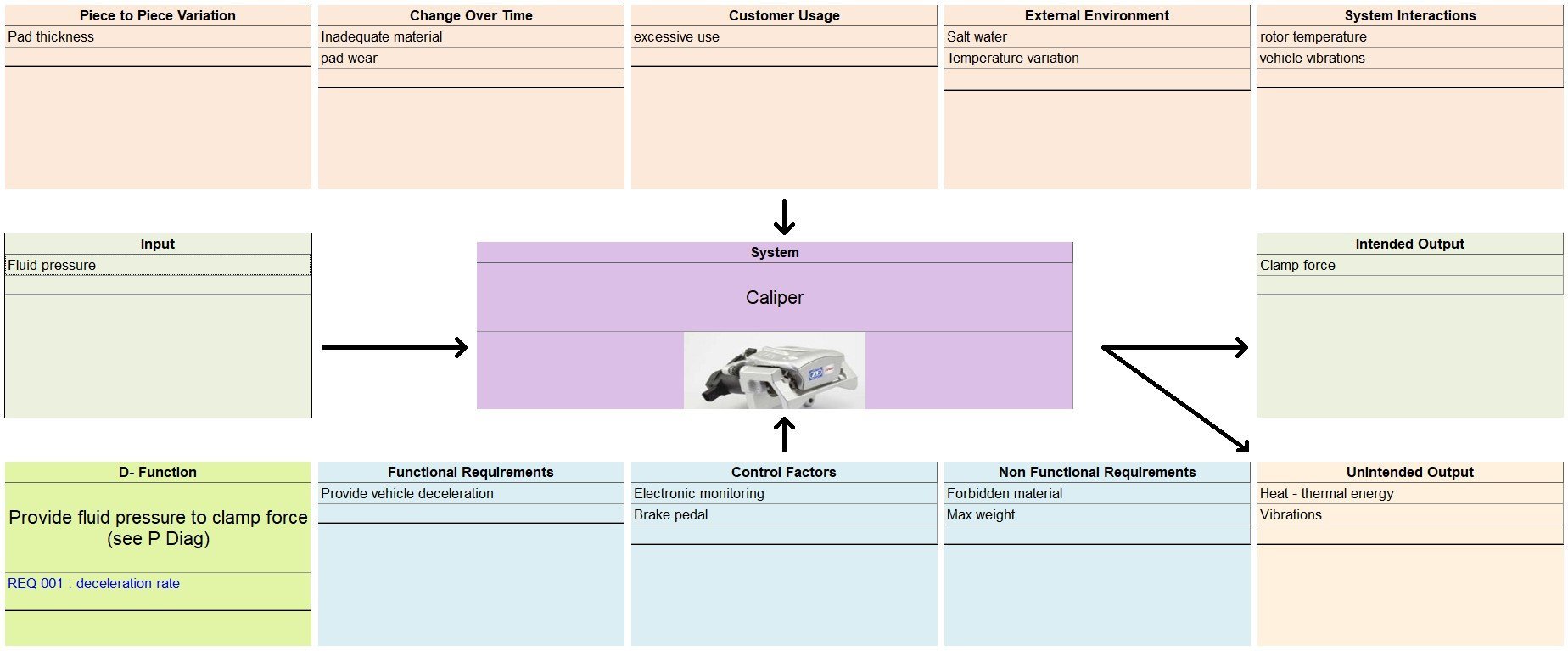
P-Diagram Excel template to identify Functions Requirements and Potential Failure Modes. The P-Diagram is a graphic tool created before a project in addition to the products functional analysis. A Parameter Diagram P-Diagram is created prior to starting a Design DFMEA and is referenced again when creating a Process PFMEA.
Many companies have already decided to use this tool before the official recommendation of the AIAGVDA guideline. System parameters FMEA. The P-Diagram is a useful tool in brainstorming and documenting.
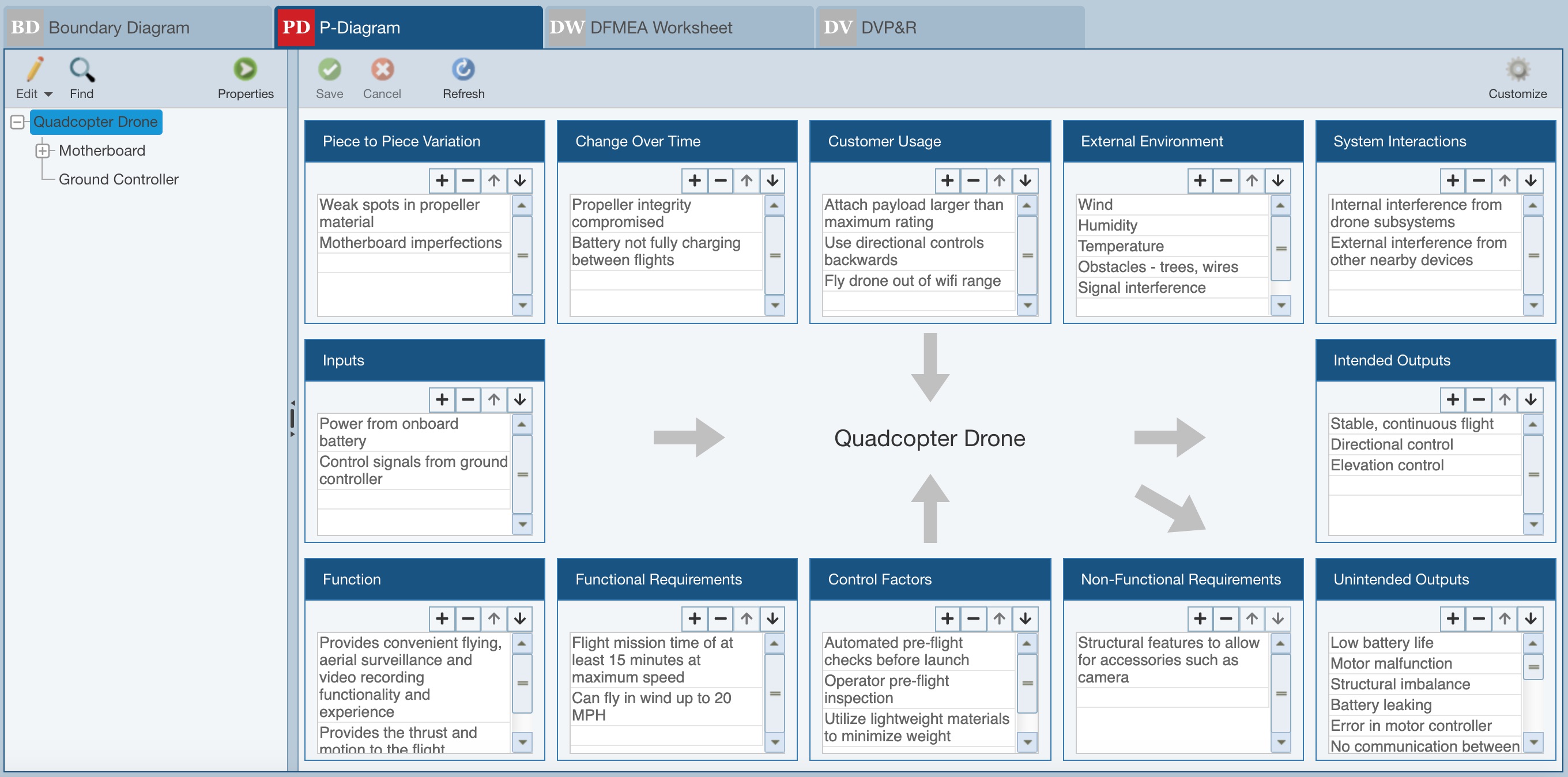
The Parameter Diagram P-Diagram takes the inputs from a system customer and relates those inputs to desired outputs of a design that the engineer is creating also considering non-controllable. Ishikawa diagram pertama kali diperkenalkan oleh Kaoru Ishikawa dan termasuk sebagai salah satu dari tujuh metode dasar dalam pengendalian kualitas 12. The input signals from the systemcustomer and the functions or outputs produced by the item under investigation are enumerated in the P-Diagram.
What is Process Failure Mode and Effects Analysis PFMEA PFMEA is a methodical approach used for identifying risks on process changes. It is most useful when the item being analyzed is a complex system with many system interactions operating conditions and design parameters as it helps the FMEA team to visually see these elements. Geometry and dimensions are cascaded waterfall into special characteristics which can be transferred to the Process FMEA.
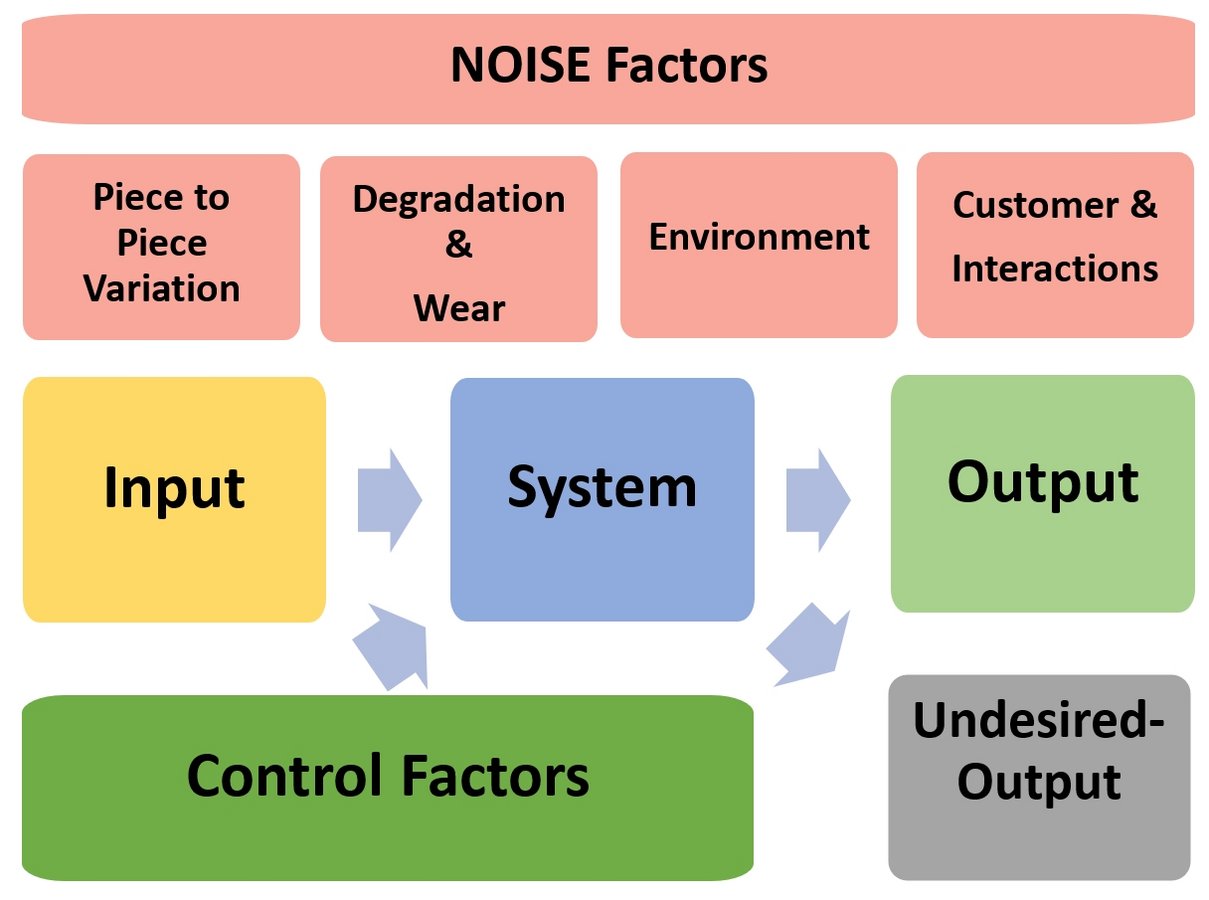
The P-Diagram includes the followingcomponents and relations. Creating a P-Diagram is an optional step when preparing a System or Subsystem FMEA. DFMEAs optionally include the creation of a P-Diagram.
On this topic Marc Thomas Noeske from Tenneco presented the PLATO webinar Anticipate the Unanticipated - Variables for Robust Design to about 125 participants. The upper part of the template is the header which includes general information on FMEA analysis and document and track information. The P-Diagram is an excellent tool for preparing risk analyses such as FMEAs.
Note that by default P-Diagrams are not enabled in Relyence Analyses. Signal Factors Response Variable or Ideal Function Control Factors Noise Factors Error States or the failure modes P- Diagram is essentially a schematic diagram that encompasses signal factor control factor noise factor and response variable. It is useful in brainstorming and documenting and helps the FMEA team understand and make visible the.
At the system level a P-diagram and FMEA can be part of the concept generation and selection process for the system as described in Chapter 8 and the system-level FMEA is included in the flowchart for identification of critical. Get the Boundary Diagram this helps define the scope of the FMEA Get the Interface Matrix P-Diagram Process Flow Chart identify the sources of variation Include a reference to rating tables General header List all assumptions in detail in the first couple of lines of the FMEA Note the part name number in the header. P-Diagrams and DFMEA System requirement flow-down also involves anticipation of potential problems.
Preventive measures recommended during a process FMEA can often lead to changes in the design. It is a clear advantage if the result of the design FMEA is available when the process FMEA is made. Process FMEA P-FMEA It is important to establish a reliable communication of information between the various development phases.
It is most useful when the item being analyzed is a complex system with many system interactions operating conditions and design parameters as it helps the FMEA team to visually see these elements. PFMEA Template for FMEA AIAGVDA Download template Each FMEA template has 2 parts. Parameter Diagrams P-Diagrams A Parameter Diagram P-Diagram is a structured tool that identifies the inputs to a system and relates those inputs to the desired system outputs while considering the controlled and uncontrolled factors.
P-Diagram Elements Creating a P-Diagram is an optional step when preparing a System or Subsystem FMEA. The P-Diagram appears in the AIAG 4th Edition manual. These can be derived from pre-work documents such as Boundary or Block Diagrams Parameter P Diagrams and Interface Analysis.
It is the ideal starting point of the FMEA. To review how to turn on P-Diagrams in your Analysis see the FMEA Properties topic for more details. A P-Diagram or Parameter Diagram is a useful tool used to determine and document inputs and intended.
The Process FMEA initially identifies process functions failure modes their effects on the process. Tim FMEA dan perusahaan yang memutuskan seberapa jauh tim harus melakukan perubahan.
P Diagram Parameter Diagram For Fmeas Aiag 4th And Aiag Vda
The P Diagram A Supporting Tool Or The Complete Confusion Risknet
P Diagram Parameter Diagram For Fmeas Aiag 4th And Aiag Vda
Fmea Executive Fault Tree Event Tree P Diagram Control Plan Process Flow Chart



Post a Comment