A Sequence Diagram Vertical Arrows Represent Messages From One Object To Another
Asynchronous Message Asynchronous messages dont need a reply for interaction to continue. The sequence diagram shows an exemplar or sample execution of some portion of the system under specific conditions.
It is composed of lifeline s and messages.
A sequence diagram vertical arrows represent messages from one object to another. Sign In Sign Up. Messages Communication between objects is depicted using messages. Solid arrow heads represent synchronous calls open arrow heads represent asynchronous messages and dashed lines represent reply messages.
Figure a sequence diagram. A sequence diagram shows as parallel vertical lines lifelines different processes or objects that live simultaneously and as horizontal arrows the messages exchanged between them in the order in which they occur. A message is a horizontal solid arrow from the lifeline of one object to the lifeline of another object.
UML 2 Tutorial - Sequence Diagram Sequence Diagrams. Sign In Sign Up. In sequence diagrams a message is shown as a horizontal solid arrow from the lifeline of one object to the lifeline of another object.
This dashed vertical line shows the sequential events that occur to an object during the charted process. However sequence numbers are. The arrow can also be labeled with a sequence number to show the sequence of the message in the overall interaction.
A Sequence diagram is an interaction diagram that details about the operation that is carried out. In the case of a message from an object to itself the arrow may start and finish on the same. The lifeline initiating the sequence of messages is Registrar.
A communication diagram emphasizes the organization of objects whereas a sequence diagram emphasizes the time ordering of messages. The Sequence diagram shows the message flow from one object to another object. The sequence diagram captures the interaction between the objects in the context of collaboration.
A sequence diagram shows as parallel vertical lines lifelines different processes or objects that live simultaneously and as horizontal arrows the messages exchanged between them in the order in which they occurThis allows the specification of simple runtime scenarios in a graphical manner. The vertical axis is the time axis and time extends downward along the vertical line. Sequence Diagrams are time focus and they show the order of the interaction visually by using the vertical axis of the diagram to represent time what messages are sent and when.
Some UML modeling software such as IBMs Rational Rose will automatically convert a sequence diagram to a communication. The Registrar sends a addCourse UML message to a RegistrationManager. In a sequence diagramvertical arrows represent messages from one object to another.
A message is a communication between objects that conveys information with the expectation that activity will ensue. UML Sequence Diagrams are interaction diagrams that detail how operations are carried out. A sequence diagram shows as parallel vertical lines lifelines different processes or objects that live simultaneously and as horizontal arrows the messages exchanged between them in the order in.
A sequence diagram is a behavior diagram that represents the interaction between objects over a specific period of time. Synchronous Message A synchronous message requires a response before the interaction can continue. 21 The messages may be synchronous shown with a solid arrowhead asynchronous shown with an open arrowhead or flow.
It portrays the communication between any two lifelines as a time-ordered sequence. The sequence diagram represents the flow of messages in the system and is also termed as an event diagram. Add the messages to the diagram by drawing arrows to represent the messages being passed from object to object with the arrow pointing in the messages transmission direction.
The sequence diagram example here is a sequence diagram for adding a course. In a sequence diagram vertical arrows represent messages from one object to another. We represent messages using arrows.
It depicts the objects and classes involved in the scenario and the sequence of messages exchanged between the objects needed to carry out the functionality of the scenario. A sequence diagram is an interaction diagram that emphasizes the time-ordering of messages. Lifelines and messages form the core of a sequence diagram.
The RegistrationManager then sends a create message to the Course class. They capture the interaction between objects in the context of a collaboration. The arrow is labeled with the name of the message operation or signal and its argument values.
In other words it represents the sequence of messages flowing from one object to another. In a sequence diagramvertical arrows represent messages from one object to another. Its usually drawn using a line with a solid arrowhead pointing from one object to another.
Sequence diagram is used to capture the time sequential interaction between objects in the operation of the system. The sequence diagram represents the interaction relationship as a two-dimensional diagram. This allows the specification of simple runtime scenarios in a graphical manner.
A sequence diagram is a form of interaction diagram which shows objects as lifelines running down the page with their interactions over time represented as messages drawn. A communication diagram will show a path to indicate how one object is linked to another. Typically youll use one sequence diagram to specify a use cases main flow.
In a sequence diagram vertical arrows represent messages from one object to another. Each vertical dotted line tail represents the time. Please continue with your Google account.
The messages appear in a sequential order on the lifeline. Types of Messages in Sequence Diagrams. Login is required in order to view results and track your progress.
Sequence diagrams are time focused and they show the order of the interaction visually by using the vertical axis of the diagram to represent time. Step 5 Place the execution occurrence on each objects lifeline by drawing a narrow rectangle box over the lifelines to represent when the classes are sending and. Incis a Canadian entertainment company that produces and markets TV programsTo generate customer interest for a new program that it is planning to.
It helps in envisioning several dynamic scenarios. Why do we use dotted lines in sequence diagram. Sequence diagram is mainly used to represent the time order.
Messages can be broadly classified into the following categories. In the above sequence diagram the arrows represent the request messages. Such an exemplar is commonly called a scenario and a single sequence diagram generally shows a single scenario.

Sequence Diagrams Csis 3600 Sequence Diagrams A Sequence
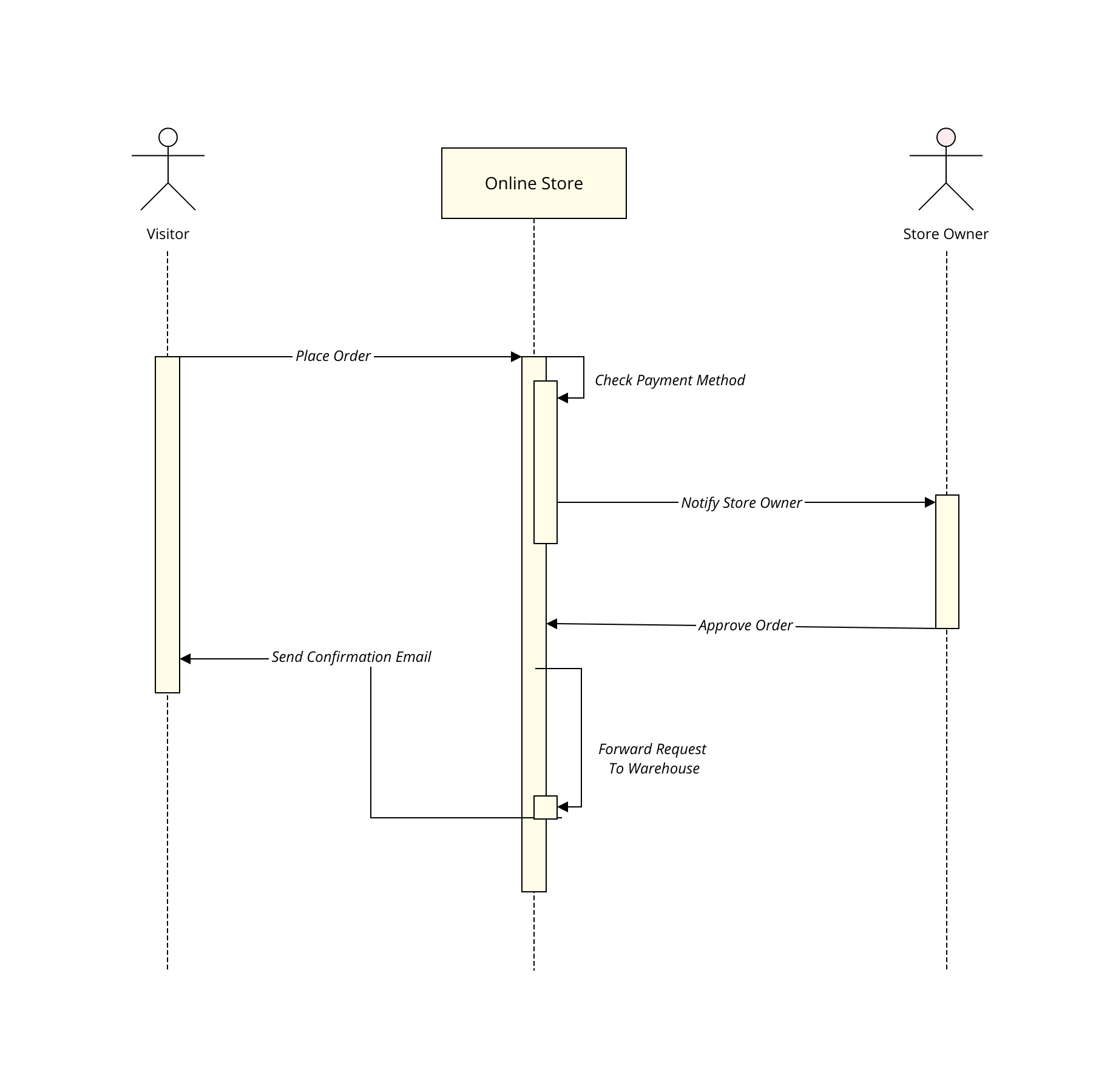
Uml Sequence Diagram Template Moqups

14 Flat Chevron Timeline Diagrams Progress Chart Steps Ppt Timeline Diagram Diagram Learning Process

Sequence Diagram An Overview Sciencedirect Topics

The Ultimate Class Diagram Tutorial To Help Model Your Systems Easily Class Diagram Tutorial Composition Pattern

Sequence Diagram An Overview Sciencedirect Topics

Bizagi Modeler Desktop Application Modeling A Process Improving Look And Feel
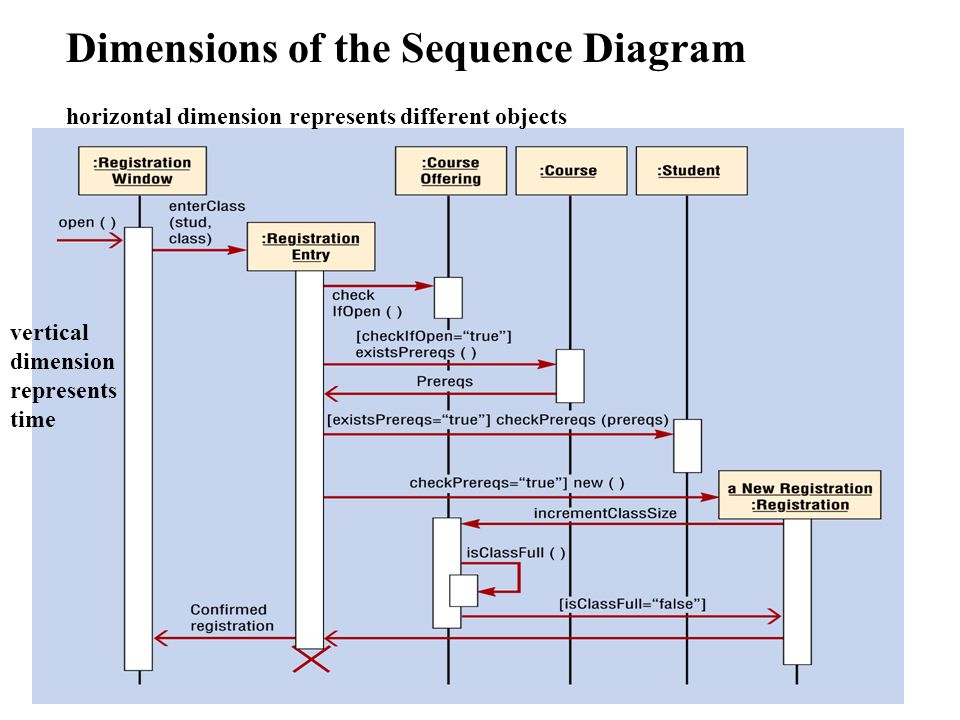
Sequence Diagrams Csis3600 Sequence Diagrams A Sequence Diagram Shows An Interaction Arranged In Time Sequence In Particular It Shows The Objects Participating Ppt Download

Sequence Diagram An Overview Sciencedirect Topics
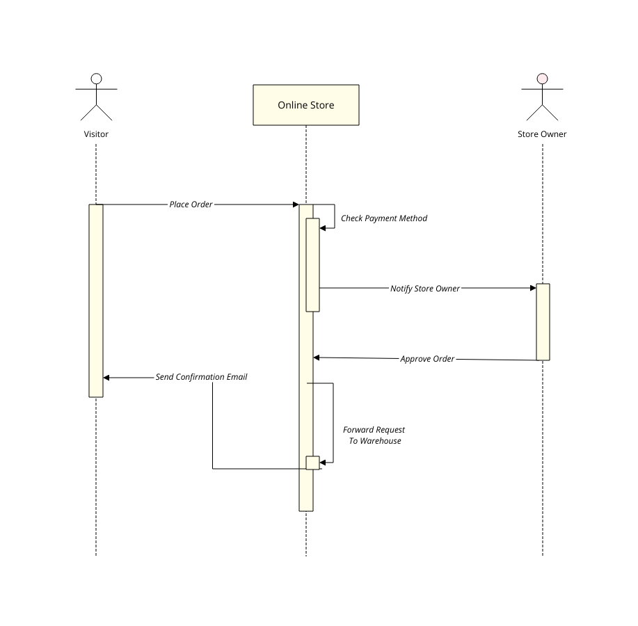
Uml Sequence Diagram Template Moqups

Post a Comment