
M N In Er Diagram
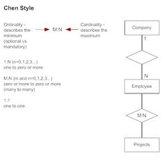
MN m and n0123 zero or more to zero or more many to many 11 one to one. 1 P a g e L a b o r a t o y o f E n t e r p r i s e A p p l i c a t i o n Modul 7.

Pin On Pa School Stuff
There are more elements which are based on the main elements.

M n in er diagram. Conversion of ER Diagram many to manyMN Relationship into Relational Table in Hindi GATE NET. Memetakan ER-Diagram ke dalam Tabel Skema Relasi dan Diagram Relasi Antar Tabel Tujuan Praktikum - Mahasiswa mampu memetakan ER diagram menjadi tabel-tabel dengan benar - Mahasiswa dapat membuat skema relasi dengan benar dari ER diagram tertentu. Cardinality and ordinality are two other notations used.
The set-theoretic perspective of the ER diagram is. Contoh mahasiswa mengambil matakuliah. Mobil Subtipe adalah suatu entitas yang merupakan.
The set-theoretic perspective of the ER diagram is. An employee is assigned to one department but may work on several projects which are not necessarily controlled by the same department. Supertipe dan Sub Tipe Supertipe adalah suatu entitas yang bersifat umum.
Entities attributes and relationships. The types of relationships that can exist between entities 11 1N and MN as well as the. Let us now learn how the ER Model is represented by means of an ER diagram.
Studentmatric_no st_name dob Modulemodule_no m_name level. Many-to-many mn relationships add complexity and confusion to your model and to the application development process. N One-to-one 11 relationships.
Beziehungen 11 1n Nm Regarding Er Diagramm 1 N M. ER diagrams Diagrammatic notation associated with the ER model 2. This module discussed the order to create an ER diagram and how entities relate to each other.
In relational database design a one-to-one 11 relationship exists when zero or one instance of entity A can be associated with zero or one instance of entity B and zero or one instance of entity B can be associated with zero or one instance of entity A. A new relation is produced which contains the primary keys from both sides of the relationship. If you have some mn relationships in your ER model then these are mapped in the following manner.
For ER Diagrams Specify structural constraints on Relationships Replaces Cardinality ratio 11 1N MN and singledouble line notation for Participation constraints Associate a pair of integer numbers min max with each participation of an entity type Ein a relationship type Rwhere 0 min max and max 1. One-to-one 11 One-to-many 1. N 1 on the side of E1 and n on the side of E3 relationship R13.
They are weak entity multi valued attribute derived attribute weak relationship and recursive relationship. If you would like get this diagram click on the image immediately and do as the way it clarifies within the photo. These primary keys form a composite primary key.
STEPS IN DATABASE DESIGN. Note that the approach described here for mapping MN relationships from the E-R diagram to the relational model could be applied as an alternative to what was described in Steps 3 and 4 to 11 1N and N1 relationships. Any object for example entities attributes of an entity relationship sets and attributes of relationship sets can be represented with the help of an ER diagram.
E1 has two single-valued attributes a11 and a12 of which a11 is the key attribute. The key to resolve mn relationships is to separate the two entities and create two one-to-many 1n relationships between them with a third intersect entity. Mungkin tidak setiap entitas mempunyai hubungan atau beberapa di antaranya malah memiliki relasi yang banyak tapi itu tidak.
ER Diagram stands for Entity Relationship Diagram also known as ERD is a diagram that displays the relationship of entity sets stored in a database. Get the ER diagram now. What does the letter N on a relationship line in an Entity Relationship diagram mean.
But also by common sense it is redundant because we would expect that the lecturers teaching a student would be derivable from the lecturers teaching the subjects of the classes the student attends. An entity-relationship ER diagram can be created based on these three types which are listed below. Example A customer can buy any number of products and a product can be bought by many customers.
1N n0123 one to zero or more. Consider the following ER diagram- Here One student can enroll in any number zero or more of courses. Contoh Diagram ER Fakultas MahasiswaDaftar miliki ambil 1 1 n n Dosen Mata Kuliah miliki ambil ajar n m 1 n 23.
Before we get into the usual mistakes found in ER diagrams it is important to understand the possible relationship types. The intersect entity usually contains attributes from both connecting. Er Diagramme 2.
You will get this diagram at no cost. ER diagrams are created based on three basic concepts. Cardinality in dbms 11 1N M1 MN Cardinality Ratio in ER diagram with example - YouTube.
There are three types of relationships between entities. N relationship R12 E1 and E3 are connected by a 1. Attributes on MN relationship types must be specified as relationship attributes 19 CONTROLS Percent.
1N MN PARTICIPATION CONSTRAINTS. We store each employees name first last MI Social Security number SSN street address salary sex gender and birth date. Partial or total PARTICIPATION CONSTRAINT An employee MUST work for a department An employee entity can exist only if it participates in a WORKS_FOR relationship instance Thus its participation is TOTAL Only some employees manage departments The participation is PARTIAL A formal constraint.
Draw an ERD for the following description. Many-to-One Cardinality- By this cardinality constraint An entity in set A. What is ER Diagram.
SUMMARY OF ER DIAGRAM SYMBOLS 20 1 E 1 entity can be related to N E 2. Types of participation entities have in relationships mandatory or optional. You explored two related but different aspects of entity relationships.
Most ERD mistakes are essentially erroneously-defined relationships between entities. One course can be enrolled by any number zero or more of students. Setelah kamu sudah membuat beberapa contoh entitas yang terhubungkan oleh garis dan membuat diamond di antara kedua entitas tersebut berarti semua hubungan telah mempunyai deskripsi masing-masing.
In other words ER diagrams help to explain the logical structure of databases. Many to many relationship MN. Er Diagramm 1 N M This is one of the instances of ER Diagram.
Consider an Entity-Relationship ER model in which entity sets E1 and E2 are connected by an m. Mahasiswa ambil Matakuliah Nim Nama Kd_mk Nm_mk n m 22. M - ordinality - describes the minimum ordinal vs mandatory N - cardinality - describes the miximum.
Entities are represented by means of. Judging by the names of entities relationships using common sense ie guessing because the diagram doesnt say lecturer-Teaches-student would be MN.

Participation Constraint A Formal Constraint Min Max Where M N Are Min And Max Number Of Relationship Diagram Management Information Systems Relationship

2006 Bent S Pln And Ple Front Step Periodic Tables Periodic Table Chemistry Ordinal Numbers

Glutamate Uptake Assay Estrogen And Tamoxifen Reverse Manganese Induced Glutamate Transporter Impairment In Astrocytes Oestrogen Glutamate Manganese
Mintzberg S 5ps Of Strategy Powerpoint Template Slidesalad Powerpoint Templates Powerpoint Strategies

Er Diagram Template For Car Rental System Relationship Diagram Relationship Database Design

Chen Style Cardinality Erd Relationship Diagram Diagram Domain Knowledge

Ink In Pdca Change Management Leadership Activities Leadership Coaching

Periodic Table Database Chemogenesis Chemistry Classroom Chemistry Periodic Table Periodic Table
Chen Style Cardinality Erd Relationship Diagram Diagram Domain Knowledge

Ksu Viticulture Canopy Managment Grape Vine Trellis Garden Vines Grape Vines

Relational Database Design Chapter 4 Exploring Relational Database Theory And Practice Page 5 Relational Database Database Design Computer Database

E Commerce Order Process Flowchart Editable Ecommerce Order Process Flowchart Template To Visualize And Id Flow Chart Business Flow Chart Flow Chart Template

Pin On Chemia 1

An Example Of Uml Activity Diagram Which Shows How To Resolve An Issue In A Software Design Activity Diagram Business Analysis Computer Generation

Post a Comment